How to Transfer Data from Siemens to Azure IoT Hub
Open Automation Software can be used to transfer data from a Siemens device to Azure IoT Hub, locally or over a network. This guide walks you through downloading and installing OAS, configuring a Siemens connector, a tag and an Azure IoT Hub publisher, and finally publishing the tag using the Azure IoT Hub publisher.
For this guide on how to transfer data from a Siemens device to Azure IoT Hub you will need:
- A Siemens device connected to your workstation with an analog input connected
- An Azure account with access to the Azure console
1 - Download and Install OAS
If you have not already done so, you will need to download and install the OAS platform.
Fully functional trial versions of the software are available for Windows, Windows IoT Core, Linux, Raspberry Pi and Docker on our downloads page.
On Windows, run the downloaded setup.exe file to install the Open Automation Software platform. For a default installation, Agree to the End User License Agreement and then click the Next button on each of the installation steps until it has completed.
If you'd like to customize your installation or learn more, use the following instructions:
The OAS Service Control application will appear when the installation finishes on Windows.
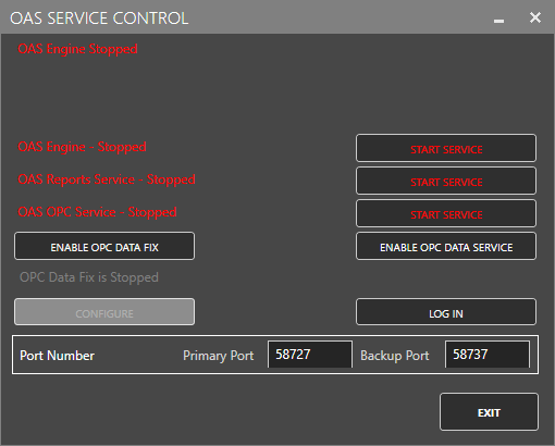
Click on each START SERVICE button to start each of the three OAS services.
2 - Configure OAS
Configure OAS is the main application used to configure local and remote OAS instances.
![]()
From your operating system start menu, open the Configure OAS application.
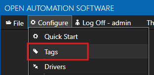
Select the Configure > Tags screen.
Important
If this is the first time you have installed OAS, the AdminCreate utility will run when you select a screen in the Configure menu. This will ask you to create a username and password for the admin user. This user will have full permissions in the OAS platform.
For further information see Getting Started - Security.
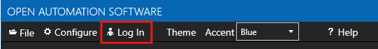
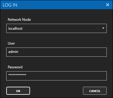
If this is the first time you are logging in, you will see the AdminCreate utility. Follow the prompts to set up your admin account. Otherwise, select the Log In menu button and provide the Network Node, username and password.
Info
In this guide you will use the Configure OAS application to configure the local Network Node which by default is localhost.
If you have installed OAS on a remote instance you can also connect to the remote instance by setting the relevant IP address or host name in the Network Node field.
3 - Configure Siemens Data Source
In the following steps you will create and configure an Siemens Connector using an Siemens driver type. This guide assumes that you have an S7-1200 or similar series controller connected to the same network as the OAS instance.
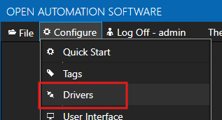
Select Configure > Drivers from the top menu.
Enter a meaningful Driver Interface Name to give this driver interface instance a unique name.
Ensure the following parameters are configured:
- Driver: Siemens
- IP Address: Your controller IP address
- Processor Type: S7 1200 (or your own controller type)
- Link Type: PC
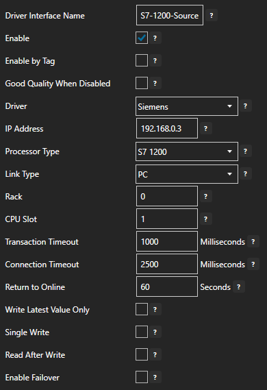
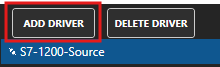
Click on the ADD DRIVER button on the left hand side to add this driver configuration. Once added, the driver interface name should appear in the list of drivers.
4 - Add Data Source Tag
In this section you will create a Tag to represent your data point in the field (for example a temperature sensor). This can then be transferred your desired destination.
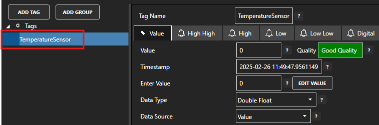
Select Configure > Tags from the top menu.
If you want to add a Tag to the root Tags group make sure the Tags node is selected in the tag list and click on the ADD TAG button.
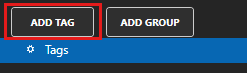
If you want to add a Tag to a Tag Group, select the Tag Group first and then click on the ADD TAG button.
You can also add Tag Groups by using the ADD GROUP button.
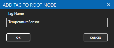
Provide a Tag Name such as TemperatureSensor and click the OK button.
5 - Assign Siemens as Tag Data Source
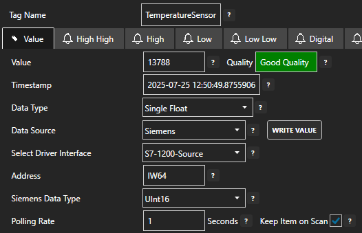
You will now set the Tag's data source to the Siemens driver interface that you created previously.
Select the Tag that will source data from a Siemens data source.
Set the Data Source to Siemens.
Set the Select Driver Interface drop-down to the S7-1200-Source interface created previously.
In the Address field enter the address of an analog input (for example IW64). Adjust the Siemens Data Type if required.
Info
For more information about Siemens addressing see the article Siemens Address Syntax
Optionally, in the Gain and Offset fields enter a value to adjust the raw value. For example, let's say you have a temperature sensor with a range of 0-50 degC and the Siemens analog value typically has a maximum value of 27648 then you would calculate the Gain as follows:
Gain    = 50 / 27648 = 0.0018084
Offset  = 0
Click on the Apply Changes button to apply the changes.
Check that the quality status is Good Quality and the data in the Value field is as expected.

6 - Create Azure IoT Hub Resource
In this step you will create a new Azure IoT Hub resource. This creates the necessary IoT broker and management framework.
Login to the Azure Console and select the IoT Hub service.
Click on the Create button.
Select your Subscription and Resource group, then provide an IoT hub name such as OASIoTHub. You can adjust the Region if necessary. For the purposes of this guide you can use the Free tier.
If you already have an IoT Hub configured you can use that instead.
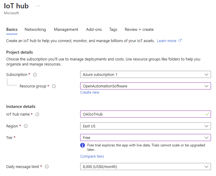
Click on the Review + create button and then click on the Create button when you have reviewed the details.
It will take a few minutes to create a new IoT Hub resource.
7 - Configure Azure IoT Hub Connector
In the following steps you will create and configure an Azure IoT connector.
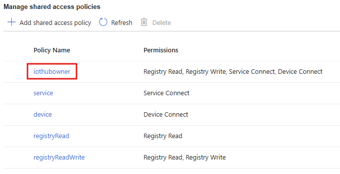
The OAS Azure IoT connector can automatically create the device in Azure that represents the OAS connection. For this reason it uses the iothubowner shared access policy.
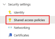
You can obtain the OASIoTHub connection string in the IoT Hub portal. Open the IoT Hub that you created and in the menu select Security Settings > Shared access policies.
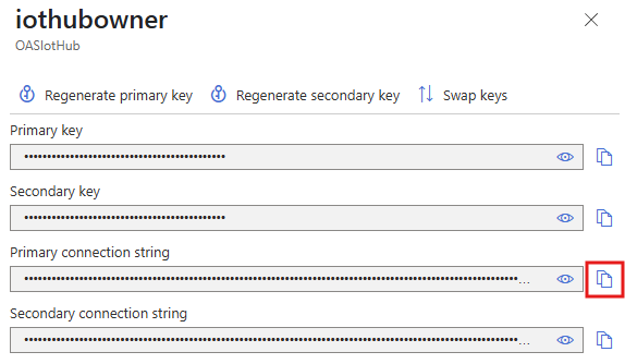
Click on iothubowner to open the key and connection strings panel.
Next to the Primary connection string click on the copy button.
In the Configure OAS application, select Configure > Drivers from the top menu.
Enter a meaningful Driver Interface Name to give this driver interface instance a unique name.
Ensure the following parameters are configured:
- Driver: Azure IoT
- Type: IoT Hub
- Azure IoT Device ID: OAS
- Azure IoT Connection: The connection string copied from Step 3
- Azure IoT Hub: OASIoTHub.azure-devices.net
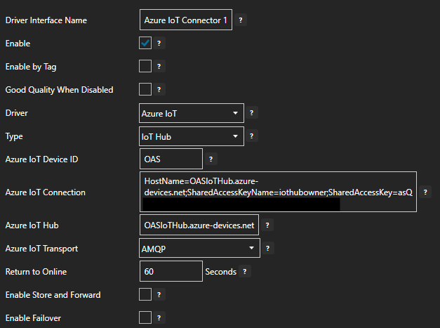
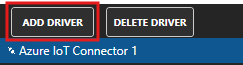
Click the ADD DRIVER button on the left hand side to add this driver configuration. Once added, the driver interface name should appear in the list of drivers.
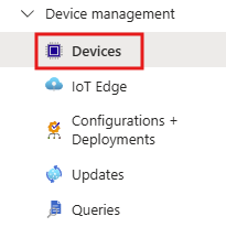
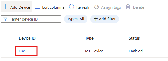
8 - Verify Azure IoT Hub Device
In this section you will verify that a device with the Device ID OAS was created automatically in the Azure IoT Hub.
In the Azure IoT Hub portal for the OASIoTHub IoT Hub, select Device management > Devices.
You should see the device OAS listed in the table.
9 - Publish Selected Tags in Azure IoT Hub connector
In this step you will select the Tags that you want to publish to Azure IoT Hub in the Azure IoT connector configuration.
In the Configure > Drivers screen, select the Azure IoT driver instance that you created in the previous section (for example Azure IoT Connector 1).
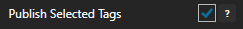
Make sure the Publish Selected Tags checkbox is ticked.
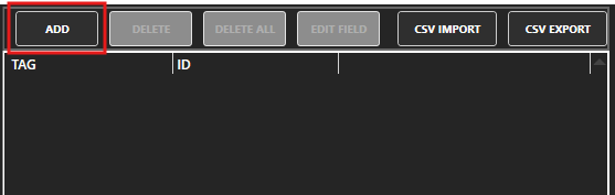
In the table at the bottom click on the ADD button.
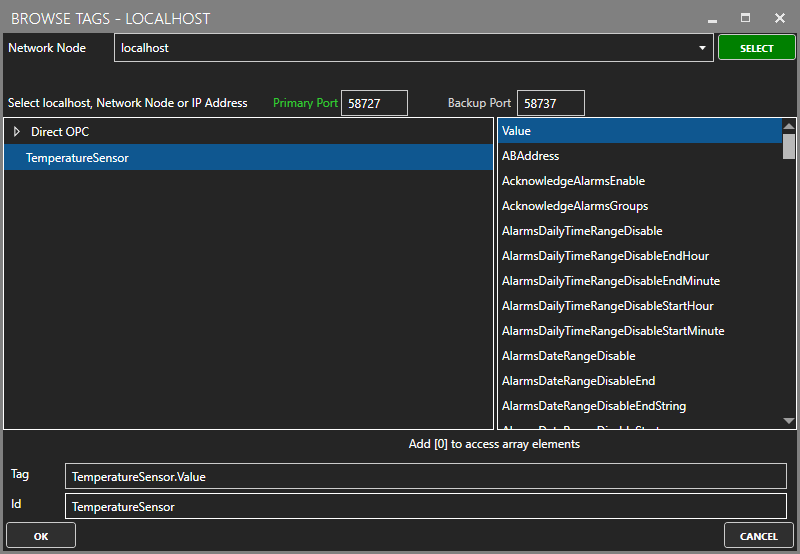
Select the Tag you want to add in the left hand panel and then ensure the Value property is selected. By default the name of the property will be the full Tag path (e.g. TemperatureSensor.Value). If you want to set your own property name, you can change the Id field to your own custom value.
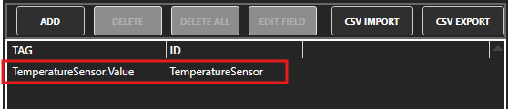
The Tag has now been added to the list. You can add other Tags by repeating steps 3 and 4.
Click on the Apply Changes button.
10 - Verify Messages are Published to Azure IoT Hub
In this step you will confirm that OAS is successfully publishing your selected Tags to the Azure IoT Hub. By default, the publishing type is set to Continuous and the interval is 10 seconds.
In the Azure portal open the Cloud Shell in the toolbar.
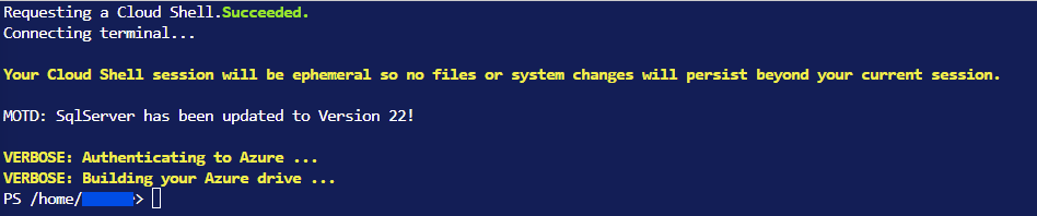
Use the following command to start listening for events.
az iot hub monitor-events --hub-name OASIoTHub --device-id OASIt may request for installation of the Azure IoT commands
You should see a payload printed for each message that is received. This should occur every 10 seconds.
Starting event monitor, filtering on device: OAS, use ctrl-c to stop...
{
    "event": {
        "origin": "OAS",
        "module": "",
        "interface": "",
        "component": "",
        "payload": "{\r\n  \"deviceId\": \"OAS\",\r\n  \"values\": [\r\n    {\r\n      \"id\": \"TemperatureSensor\",\r\n      \"value\": \"24.902344\",\r\n      \"quality\": true,\r\n      \"timestamp\": \"2025-05-14T07:52:30.576Z\"\r\n    }\r\n  ]\r\n}"
    }
}
The data from OAS is contained in the
payloadfield of the JSON structure.To stop monitoring you can press
ctrl-con your keyboard.
11 - Save Changes
Once you have successfully configured your OAS instances, make sure you save your configuration.
On each configuration page, click on the Save button.
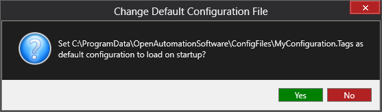
If this is the first time you are saving the configuration, or if you are changing the name of the configuration file, OAS will ask you if you want to change the default configuration file.
If you select Yes then OAS will make this configuration file the default and if the OAS service is restarted then this file will be loaded on start-up.
If you select No then OAS will still save your configuration file, but it will not be the default file that is loaded on start-up.
Important
Each configuration screen has an independent configuration file except for the Tags and Drivers configurations, which share the same configuration file. It is still important to click on the Save button whenever you make any changes.
For more information see: Save and Load Configuration
Info
- On Windows the configuration files are stored in C:\ProgramData\OpenAutomationSoftware\ConfigFiles.
- On Linux the configuration files are stored in the ConfigFiles subfolder of the OAS installation path.