Web HMI Graphics
NOTE: If you want to visualize your data in a desktop or mobile browser with zero programming, you may be interested in the OAS Open UIEngine .
The UIEngine is a robust no-code web application and HMI builder for developing rich user interfaces in a browser-based development environment.
See the UIEngine Documentation to learn more.
Using image tags in Web HMI
Many applications require some dynamic graphical elements to indicate value changes on the server. The simplest example may be an image of a switch changing from the “on” state to the “off” state depending on the value of a Boolean server tag.
In more complex implementations, multiple tags can be used to change the state of an HTML image, allowing more nuanced visual representations of data. Such an implementation could use multiple images to represent a motor in various states such as “running”, “idle”, “running and overheated”, “idle and overheated”, as well as an image to indicate bad data quality received from the server for this element.
Web HMI Graphics Introduction
In this example, we are going to configure an HTML image tag using Web HMI attributes in order to indicate the various states of a valve. The end result will appear to change the color of the valve between red, green, and yellow to indicate when the valve is closed, open, or receiving bad data, respectively.
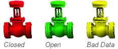
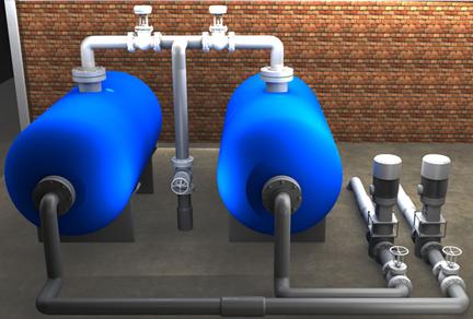
These images will be superimposed on a background depicting the entire system, so operators can see the physical layout as well as the data.
Setting the Stage for Web HMI Graphics
The first step is to create an HTML page with the necessary script library references and configuration. To learn more about how to set up a basic Web HMI page, see this tutorial.
Once you have a basic page configured, you’ll add a CSS stylesheet section to the HTML <head> element which will be the place where we define the layout and positioning of elements. It should look like this:
<head>
  // script references go here…

  <style>

    #bkg_image {
      position:relative;
      width:767px;
      height:518px;
      background: url(images/new_tanks/Background.jpg) 0 0 no-repeat;
    }

    #valve1 {
      position:absolute;
      top:9px;
      left:206px;
    }

  </style>

</head>
The #bkg_image entry refers to an element with the id of “bkg_image”. This will be the container for the valve image and will have a background image set within it. The background is the physical layout of the system.
The #valve1 entry refers to an element with the id of “valve1”, which will be the image of the valve itself. As mentioned above, this will use absolute positioning, but will be relative to the container.
More about CSS
If you’re not familiar with CSS, setting the position to relative means that anything contained within it will be positioned relative to the container itself. So if we set a coordinate for anything within it, they will always be relative to the background image. The width, height, and background settings are pretty straightforward. If you want to learn more about CSS, you can visit the W3Schools site.
Adding the elements to the page
The next step is to add the background and valve elements to the page. Your HTML <body> should look like this:
<body>

  <div id="bkg_image">
    <img id="valve1"
      oas-tag-src='{"type":"group",
        "group":[
          {"tag":"WPF.New Tanks Demo.Tank1 Inlet Valve.Value","config":"images/new_tanks/ValveTopLeft_Green.png"}
        ],
        "all_f":"images/new_tanks/ValveTopLeft_Red.png",
        "bad_q":"images/new_tanks/ValveTopLeft_Yellow.png"
      }'
    />
  </div>

</body>
The oas-tag-src attribute applied to an <img> tag will change the image source based on the value of Open Automation Software Server tag values. The first setting is “type”:”group”. This tells the framework that we’re using a “group” attribute because we’ll be applying a group of tags. This is similar to the oas-tag-bg, oas-tag-fg, and others.
The next setting is the group itself. This is a list of tags and configurations to apply when the tag evaluates to a Boolean True. The structure follows this format:
"group":[
  {"tag":"YourTagName.Value","config":"image url"},
  {"tag":"AnotherTagName.Value","config":"image url"},
  …
]
Each tag in the group list is evaluated in the order it is written. The first tag that evaluates as True will have its configuration applied, and no others will be checked. In this example, we only have one tag in the list, but you could add others to indicate values such as “Open and high pressure”, “Open and low pressure”, changing colors for each to create a more nuanced interface.
The “all_f” setting applies an image URL when all of the tags within the group evaluate to False, and the “bad_q” setting applies an image URL when any tag within the group is sending bad data quality to the browser.
Making the image clickable
Displaying a dynamic image on a layout is very useful, but to make an HMI interactive, you’ll want to make the image clickable, letting operators open and close a valve remotely.
To achieve this, modify the <img> tag to look like this:
img id="valve1"
  oas-tag-src='{"type":"group",
    "group":[
      {"tag":"WPF.New Tanks Demo.Tank1 Inlet Valve.Value","config":"images/new_tanks/ValveTopLeft_Green.png"}
    ],
    "all_f":"images/new_tanks/ValveTopLeft_Red.png",
    "bad_q":"images/new_tanks/ValveTopLeft_Yellow.png"
  }'
  oas-tag-set='{"tag":"WPF.New Tanks Demo.Tank1 Inlet Valve.Value",
    "config":{"evt":"click","set":"toggle"}}'
/>
The oas-tag-set attribute makes the image active, responding to a click event. When the image is clicked, it sends a “toggle” message to the server to switch the Boolean value to the opposite of the current state. You’ll notice that the “tag” setting of this attribute matches the “tag” in the oas-tag-src. This ensures that clicking the image will set the same tag being used for display purposes.
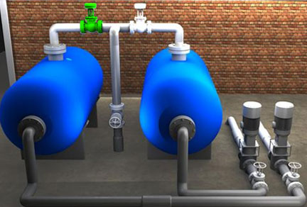
The end result
After all pieces are put together, and you run the example in a browser, you should see the following result. Notice the green valve overlaid on the background to indicate that the valve is open:
Using this same technique, you can place additional dynamic images on a physical layout to achieve a fully functional HMI in a web page. An example of this fully functional HMI can be found by going to www.opcweb.com.
The source of the full online example is installed with Open Automation Software in:
C:\Program Files\Open Automation Software\OAS\HTML_HMI\Example\html_hmi_demo.zip