Connectors
Connectors are dynamic visual elements that indicate a path between Components. They can be driven by OAS Tags and will adjust themselves as the connected Components are repositioned. Useful for indicating process, data, or material flows.
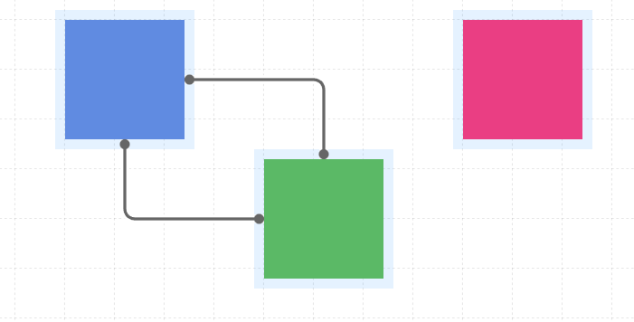
Connect Mode
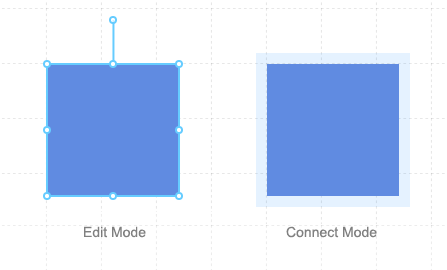
Within the Editor, Connectors can be added, adjusted, or removed only while in Connect Mode. To enter Connect Mode, first enter Edit Mode by clicking the icon. Then enter Connect Mode clicking the icon when it appears.
All Components placed on the Screen will display an indicator, letting you know that Connect Mode is active. This is the blue highlighted region surrounding the Component.
Once Connect Mode is active, new Connectors can be dragged between Components, starting within the highlighted region of one Component and ending at the edge of another.
If you choose not to add a connector after you have started dragging, you can mouse up within an open area of the Screen and the operation will be cancelled.
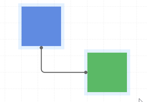
You can also reposition the start and end points for any connector, or remove it entirely by grabbing a point and dropping it in a new spot.
Styling
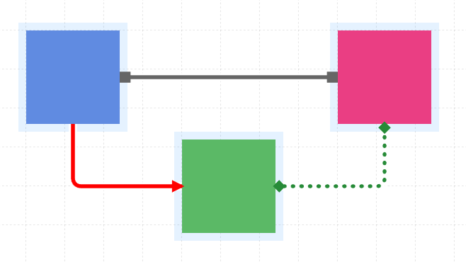
Like Components, properties of a Connector can be modified to change their appearance, and several can be driven by OAS Tags, which is useful for indicating live server states.
| Property | Type | Description |
|---|---|---|
| Width | Numeric | Pixel width of the Connector line. Adjusting the Width will also increase or decrease the end cap size accordingly. |
| Color | Color | The line color. This also applies to the end caps. |
| Style | Options | Solid, Dashed, or Dotted |
| Animated | Boolean | For Dashed and Dotted line styles, if set to true will animate the line from start to end point. |
| Cap Style | Options | Circle, Square, Diamond, and Arrow |
| Cap Position | Options | Start, End, Both, None |
| Visibility | Boolean | Determines when to show or hide the Connector |