How to Visualize Modbus Data from a WPF .NET Application

Open Automation Software Tags can be defined to connect directly to Modbus slave devices or host data to Modbus masters with the built in Modbus Driver Interface which supports communications over ethernet and serial interfaces for Modbus TCP, Modbus RTU, and Modbus ASCII protocols. This tutorial walks you though downloading and installing OAS, configuring a Modbus driver, configuring tags and visualizing tag data in .NET WPF with either C# or VB. Programming is not required if you use the designer interface.
Step 1. Download and Install the Open Automation Software and Start the OAS Service
If you have not already done so, you will need to download and install the OAS platform. Fully functional trial versions of the software are available for Windows, Windows IoT Core, Linux, Raspberry Pi and Docker on our downloads page.
On Windows run the downloaded Setup.exe file to install one or more of the Open Automation Software features. Select the default Typical installation if you are not sure what features to use or the Custom installation if you want to save disk space on the target system. When prompted agree to the End User License Agreement to continue the installation.
For more detailed instructions and video tutorials, visit the installation guide for your system:
Windows Installation | Linux Installation | Raspberry Pi Installation | Dockers Installation
The OAS Service Control application will appear when the installation finishes on Windows. Use this application to start the 3 Services. Run the Configure OAS application on Windows and select Configure-Tags; if the first time running, the AdminCreate utility will run to create an Administrator login as shown in Step 1 of Getting Started – Security.
Step 2. Configure Your Modbus Data Source
- First, you will need to open the Configure OAS application from the program group Open Automation Software.
- Select Configure >> License from the top menu and verify that Modbus is one of the available Drivers in the lower left of the form. The demo license will have this by default. If you do not see Modbus available, contact support@openautomationsoftware.com to update your license.
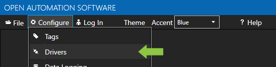
- Select Configure >> Drivers from the top menu.
- Select localhost or the remote service you wish to modify with the Select button to the right of the Network Node list.

- The Configure Drivers Screen will appear. Select Modbus from the Driver dropdown box.
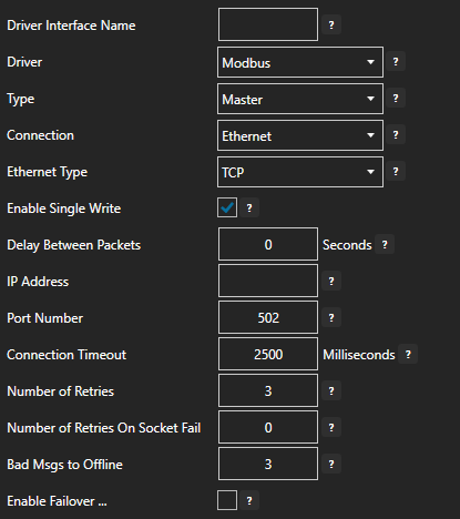
- Enter a meaningful Driver Interface Name that you will refer to this physical connection when defining Tags with a Modbus Data Source.
- Specify the Connection as Ethernet or Serial.
- Specify the Modbus Type as Master or Slave. Master will be used when communicating to a Modbus device. Slave will be used when other Modbus masters will be communicating to OAS.
- When setting up a Slave interface over Ethernet set the IP Address to the computer IPv4 IP address or network node name if the master is on a remote PC. You can also use 127.0.0.1 or localhost if the Modbus master will be on the same computer.
For more detailed instructions on configuring your Modbus data source, click here to see our Getting Started Modbus tutorial or watch the video tutorial below:
Step 3. Configure Your Tags
OAS provides multiple ways to add and define tags:
- Manually add and define Tags using the Configure OAS application. …learn more…
- CSV Import and Export …learn more…
- Programatically …learn more…
- One Click Allen Bradley …learn more…
- One Click OPC …learn more…
To add a Tag manually:
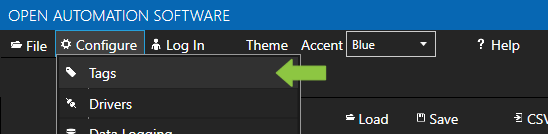
- In the OAS Configure Application, select Configure >> Tags from the top menu.
- Select localhost or the remote service you wish to modify with the Select button to the right of the Network Node list.
- Click on the Add Tag button located at the top of the Tag browser on the left portion of the screen.
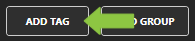
- A dialog box will appear. Enter a name for your new tag and click ok.
- A configuration screen will appear for your new tag. Select your data source type in in the Data Source dropdown box.
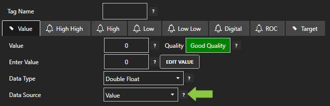
- Specify the correct data type in the Data Type dropdown box.
- Click Apply Changes at the bottom right of the window.
For more detailed instructions on configuring your tags, click here to see our Getting Started Tags tutorial.
Step 4. Visualize Your Data with .NET
Project Setup
HMI applications can be developed using Microsoft Visual Studio 2010 (or later). Programming is not required if you use the visual editor.
Open your existing Visual Studio application or start a new one, either VB or C#. Specify WPF App (.NET Framework) as the project type.
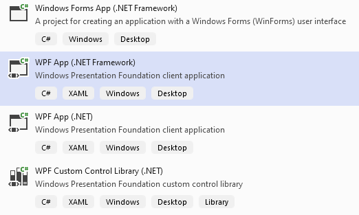
Verify that the Target Framework is Version 4.61 or greater.
If you have installed Open Automation Software after installing Visual Studio you should see the Open Automation Software group in your toolbox. If it is not there you can add a reference in your project to the OPCWPFDashboard.dll. It will be in your installation folder, most likely: C:\Program Files\Open Automation Software\OAS. Add the tools by right clicking on the toolbox and selecting Choose Items. In the Choose Toolbox Items dialog box under the WPF tab, select all of the items that start with OPCWPF and say OK.
Add a Viewbox
If you are unfamiliar with the Viewbox control in WPF it is very useful. By setting it’s Stretch property to Uniform, it will automatically transform it’s contents to fit the user’s screen. It is easier to develop with the Stretch Property set to “None” and then set it back to “Uniform” at the end. You will want your Grid inside of your Viewbox. Your XAML should look like this:

Add a Label Control
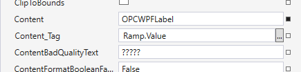
Add an OPCWPFLabel control to the window by double clicking on it in the toolbox. Set the Content_Tag property of the label to the Tag property that you want the label to display. Do this by either typing it in the box if you know the name (they are case-sensitive) or use the ellipse next to the property box. If you are using the demo tag configuration that installs with Open Automation Software use Ramp.Value.
Referencing Tags
In the tag browser, you will need to select your network node and then the tag and the property you want to display. Your network node will be the location you have Open Automation Software installed on. If it is your local machine, it will be localhost, otherwise, it could be a registered domain name or an IP address. Here are some examples of referencing tags based on their location:
Local Tag:
myTag.Value

Local Tag in a Group:
myGroup. myTag.Value

Basic Networking:
\\192.168.0.1\myGroup.myTag.Value

Live Data Cloud Networking from Local OAS Engine:
RemoteSCADAHosting.myLiveDataCloudNode.myGroup.myTag.Value

Live Data Cloud Networking from Remote OAS Engine
\\192.168.0.1\RemoteSCADAHosting.myLiveDataCloudNode.myGroup.myTag.Value
Add a Button Control
Next, add a button to the window by double clicking on OPCWPFButton on the toolbox. Use the Pump tag for the button, it is a Boolean data type. Set Content_Tag in the properties window to Pump.Value. In the ContentFormatBooleanFalse property enter The Pump is On and the in the ContentFormatBooleanTrue property enter The Pump is Off. That way the button text will be something more meaningful than simply True or False.
To change the color of the button when it’s value changes, use the Background01_Tag property. Set it to Pump.Value. The BackgroundFalse and BackgroundQualityBad properties control the background color for when the value is false and bad quality.
Next, SetValue_Tag property to Pump.Value. This specifies what value to change when the button is clicked.
Add a Radial Gauge
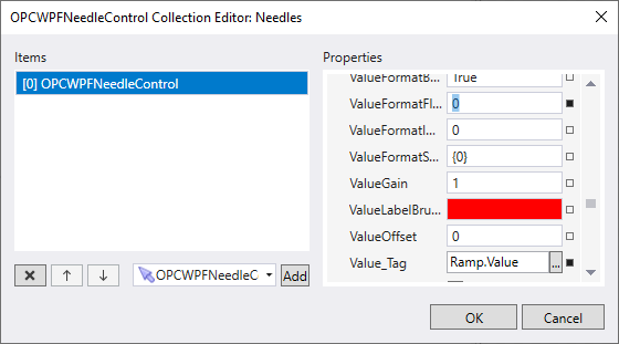
Drag an OPCWPFRadialGauge onto the screen. Click the ellipse next to the Needles property. This will open the Needles Collection dialog box. Click the Add button. This adds a Needle to the Radial Gauge. Set the Value_Tag property to Ramp.Value, the Ramp Tag again. It is a Float Data Type, enter 0 for the ValueFormatFloat property.
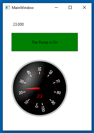
Click F5 to compile and run your project. Your screen should look similar to this.
For more detailed instructions on using OAS with WPF, visit .NET WPF HMI in our knowledge base or watch the video below:
Also, see Getting Started – .NET Trend and Getting Started – .NET Alarm.