Getting Started Modbus
Open Automation Software Tags can be defined to connect directly to Modbus slave devices or host data to Modbus masters with the built in Modbus Driver Interface which supports communications over Ethernet and Serial interfaces for Modbus TCP, Modbus RTU, and Modbus ASCII protocols.

You can view the Getting Started with Modbus Video to familiarize yourself with the following steps to setup Modbus communications.
The following steps can be used to setup direct communications with Modbus devices.
Step 1 – Check Modbus License

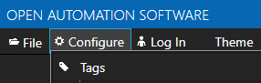
Start Configure OAS application from the program group Open Automation Software.
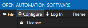
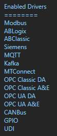
Select Configure-License and verify that Modbus is one of the available Drivers in the lower left of the form. If you do not see Modbus available contact support@oasiot.com to update your license.
NOTE: To configure remote OAS Engines enter the IP Address or node name in the Network Node field and click on Select.

Note: You will need to be running Open Automation Software Version 8 or greater to support direct Modbus communications. You can download the latest version at www.openautomationsoftware.com/downloads/open-automation-software/
Step 2 – Configure Modbus Drivers
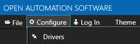
Select Configure-Drivers.
Enter a meaningful Driver Interface Name that you will refer to this physical connection when defining Tags with a Modbus Data Source.

Set the Driver type to Modbus.
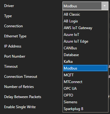
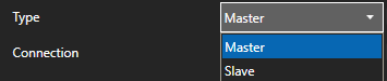
Set the Type as Master to communicate with a Modbus device. Set to Slave if OAS is to interface with one or more Modbus masters.
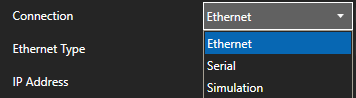
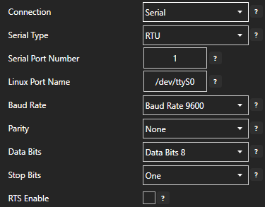
Set the Connection type as Ethernet or Serial.
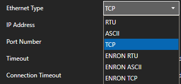
Set the Ethernet Type or Serial Type to the Modbus protocol to use. For Ethernet connections TCP is the most common. For Serial connections the most common would be RTU or ASCII. OAS supports all protocols on both connection types.
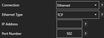
Ethernet Connection:
Specify the IP Address and Port Number. For Master connections specify the IP Address of the Modbus device. For Slave connections et the IP Address to the computer IPv4 IP address or network node name if the master is on a remote PC. You can also use 127.0.0.1 or localhost if the Modbus master will be on the same computer as OAS.
Serial Connection:
Specify the Serial Port Number for Windows or Linux Port Name for Linux.
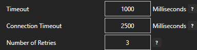
Specify Timeout and Number of Retries when a communication failure occurs.
For Master connections Enable Single Write controls how individual writes are performed.
When enabled Function Code 05 to be used when there is only one Output Coil to write, Function Code 06 to be used when there is only one Holding Register to write.
When disabled Function Code 15 will always be used for Output Coils and Function Code 16 for Holding Registers.

For Master connections Enable Multiple Write allows multiple holding registers with contiguous addresses to be sent in one packet.

Set Bad Msgs to Offline to the number of successive communication failures to stop communications to the device and retry at the rate specified in Return to Online.
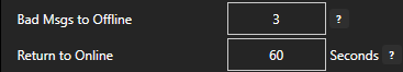
NOTE: Set Bad Msgs to Offline to 0 to leave the device online at all times.
For redundancy support optionally define a secondary failover device if the primary device fails with the property Enable Failover.
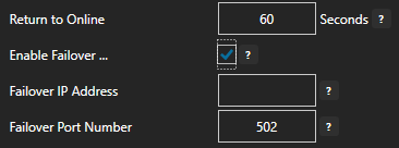
If both the primary and secondary device are offline the Return to Online settings determines the retry frequency.
View Driver Interface Failover for more information and and video demonstrating communications failover.
The Comm Bad and Comm Good properties can be used to assign an Integer Tag to be updated with the communication summary of the driver interface.
| Comm Bad Count | Will set a tag with the driver interface Comm Bad Count. The number of times the communications of the driver interface has transitioned from good to bad. Can be reset to 0 when tag defined to Comm Count Reset transition from false to true. |
| Comm Bad Read Count | Will set a tag with the driver interface Comm Bad Read Count. The number of communication reads from the device has failed for the driver interface. Can be reset to 0 when tag defined to Comm Count Reset transition from false to true. |
| Comm Bad Time | Will set a tag with the driver interface Comm Bad Time. The time in seconds the communications to the device has been bad. Can be reset to 0 when tag defined to Comm Count Reset transition from false to true. |
| Comm Bad Write Count | Will set a tag with the driver interface Comm Bad Write Count. The number of write failures to the device. Can be reset to 0 when tag defined to Comm Count Reset transition from false to true. |
| Comm Good Count | Will set a tag with the driver interface Comm Good Count. The number of times the communications of the driver interface has transitioned from bad to good. Can be reset to 0 when tag defined to Comm Count Reset transition from false to true. |
| Comm Good Read Count | Will set a tag with the driver interface Comm Good Read Count. The number of communication reads from the device has succeeded for the driver interface. Can be reset to 0 when tag defined to Comm Count Reset transition from false to true. |
| Comm Good Time | Will set a tag with the driver interface Comm Good Time. The time in seconds the communications to the device has been Good. Can be reset to 0 when tag defined to Comm Count Reset transition from false to true. |
| Comm Good Write Count | Will set a tag with the driver interface Comm Good Write Count. The number of successful writes to the device. Can be reset to 0 when tag defined to Comm Count Reset transition from false to true. |
| Comm Count Reset | Define a Boolean tag that can reset the Comm Counts and Times. A transition from false to true will reset the counts. |
Select the Add Driver button in the upper left to add the Driver Interface as an available selection when defining Tags in the next step.

Note: If you need to define several Driver Interfaces you can use the CSV Export and CSV Import on the toolbar with Microsoft Excel.

Drivers can also be programmatically assigned with the OAS REST API or .NET Server Configuration interface.
Step 3 – Configure Modbus Tags
Select Configure-Tags.
Select Add Group to add a group to place tags in.

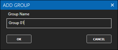
NOTE: You can add organizational Groups as many levels deep as you prefer and add tags to groups. To do this first add a Group to the root level, then right click on the Group in the right window to add additional Groups or Tags.
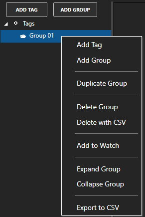
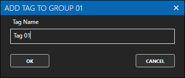
Select Add Tag to add a tag to the group selected.

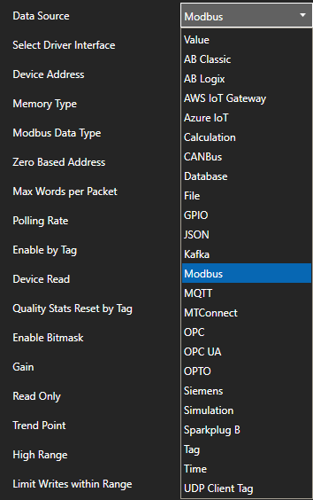
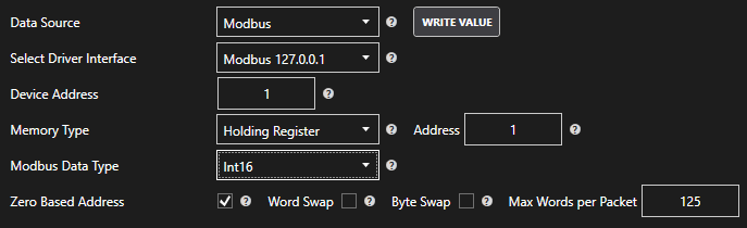
Change the Data Source Tag property to Modbus.
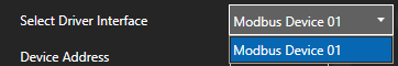
Select the correct Driver Interface from the Driver Interface pull down list.
Specify the Device Address (set as -1 if it is not to be used on Ethernet)

Select the correct Memory Type from the Memory Type pull down.
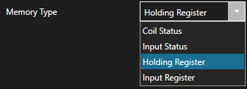
NOTE: Use the “As Boolean” types to access bits of a 16, 32, or 64 bit Integer.
Specify the Address for the memory location.
The base of the memory type will be added to the Address.
Extended addressing is also supported.
To communicate to 410001 set the Memory Type to Holding Register and the address to 10001.
To communicate to 465535 set the address to 65535.
Following are some examples.
- To access 40,001 use address of 1
- To access 49,999 use address of 9,999
- To access 50,000 use address of 10,000
- To access 410,001 use address of 10,001
- To access 420,000 use address of 20,000
- To access 430,000 use address of 30,000
- To access 440,000 use address of 40,000
- To access 450,000 use address of 50,000
- To access 460,000 use address of 60,000
- To access 465,535 use address of 65,535
NOTE: Zero Based Addressing will subtract 1 from the address when communicating to the device.

Example: Communicating to Holding Register 40000 the Memory Type will be Holding Register and the Address would be 1.
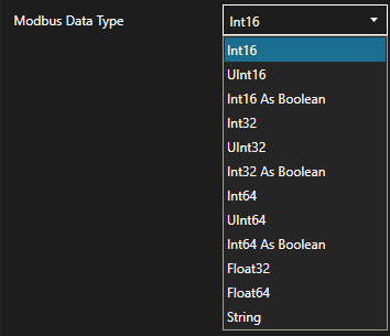
For Input Register and Holding Register Memory Types select the correct Modbus Data Type.
Word Swap and Byte Swap can be enabled to swap words or bytes within the value received or sent.

Max Words per Packet is used to control the maximum number of words allowed in each communication packet. OAS can support up to 10,000 words per packet if the device can support it. Most Modbus devices only support 125 words per packet.

Set the desired Polling Rate for reading from the device. The rate can be set to 100 nanoseconds, but the lowest practical rate would be 20 milliseconds or 0.02 seconds.

To disable communications to the device you can use Enable by Tag to control when communications is active. Leave this property disabled to establish communications at all times.

The Device Read property can be used to disable continuous polling and request data on event from the transition from false to true of a value of a Boolean tag. Leave this property disabled to establish communications at all times.

Each Modbus Tag provides communication stats for success or failure on reading and writing to a device. Use the property Quality Stats Reset by Tag to define a Boolean tag that will reset the stats on a value transition from false to true.

Select Apply Changes to make the changes active on the tag.

Check that the data quality of the tag is Good Quality and the value from the device is returned.

If the data quality is ![]() view Troubleshooting Modbus Bad Data for solutions to common errors.
view Troubleshooting Modbus Bad Data for solutions to common errors.
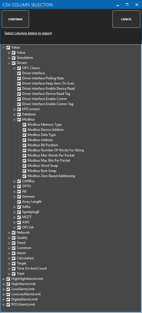
To define multiple tags use the CSV Export and CSV Import on the toolbar together with Microsoft Excel.
When exporting tags choose which columns to include in the CSV file. There are over 800 properties available for use in each tag and reducing the amount of data can help to focus on the properties of interest.
NOTE: Tags can also be programmatically assigned with the OAS REST API or .NET Server Configuration interface.
Step 4 – Save Modbus Tags and Drivers
Select the Save button on the toolbar at the top.

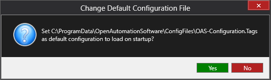
Enter a file name to be saved in C:\ProgramData\OpenAutomationSoftware\ConfigFiles directory on Windows or ConfigFiles subdirectory on Linux.
When prompted to set the file as the default configuration to load on startup select Yes.
The tags defined are now ready for use in all OAS features like Data Logging, Data Route, and Open UIEngine.