Getting Started Raspberry Pi GPIO
The Open Automation Software platform has a built in communication driver for General Purpose Input / Output when deployed on a Raspberry Pi 4. Tags can be defined to read or write to GPIO pins.

You can view the OAS GPIO Setup Video to familiarize yourself with the following steps to setup GPIO communications on your Raspberry Pi 4.
- 00:00 – Introduction
- 00:11 – GPIO Driver
- 00:16 – Written tutorial
- 00:28 – Download and Install OAS on the Raspberry Pi
- 00:53 – OAS for Linux Download
- 01:06 – Set Up Access to the GPIO Driver
- 01:48 – Reboot the System
- 01:55 – Configure the Pins
- 03:05 – Configure more tags options
- 03:32 – Knowledge Base
- 03:45 – Save changes to tag configuration
- 04:24 – Transfer data
- 05:07 – Learn More
The following steps can be used to setup communications with the GPIO pins.
Step 1 – Installation
Download and install OAS onto Raspberry Pi 4 device. View the Raspberry Pi Installation guide for an easy to following video instructions or use the Linux Installation guide for step by step instructions to use the simple install script.
Step 2 – Set Access Level
Setup access to gpiomem for the user account the OASEngine is running under. The default is oasuser.
This is achieved by adding a rules file to etc/udev/rules.d/.
Log in to the root account and change directory to etc/udev/rules.d/.
ssh ubuntu@<ip address of Raspberry Pi>
cd /etc/udev/rules.d/
Create a file oas-gpio.rules with an editor with the following contents, then save the file.
SUBSYSTEM=="gpio*", PROGRAM="/bin/sh -c 'chown -R root:oasuser /dev/gpiomem && chmod -R 660 /dev/gpiomem'"
To create and edit the file you can use nano.
sudo nano oas-gpio.rules
Reboot the system.
sudo reboot
Step 3 – Configure Tags

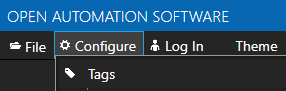
From a Windows system start Configure OAS application from the program group Open Automation Software.
Select Configure-Tags.
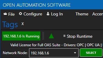
Enter the IP Address of the Raspberry Pi device and click Select.
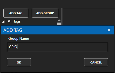
Select ADD GROUP to add the group GPIO and click OK. The group name can be anything you like, in this example it will be GPIO.
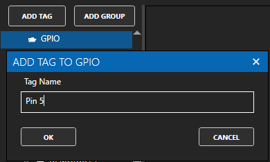
With the GPIO group selected click on ADD TAG to a tag with the name Pin 5. The tag name can be anything you desire. In this example we are assigning to GPIO Pin 5 so we will name it Pin 5.
Change the Data Type of the tag to Boolean.
Change Data Source Tag property to GPIO.
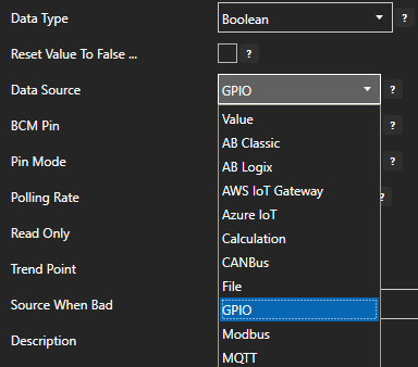
Set the Pin Mode to one of the following.
Input: Read Only – Configures the GPIO pin in floating mode, with high impedance.
InputPullDown: Read Only – Configures the GPIO pin as high impedance with a pull-down resistor to ground.
InputPullUp: Read Only – Configures the GPIO pin as high impedance with a pull-up resistor to the voltage charge connection (VCC).
Output: Write Only – Configures the GPIO pin in strong drive mode, with low impedance.
Note: A pin cannot be set to both Input and Output. Inputs are read only. Outputs are write only.
When defining the pin as an input set the desired Polling Rate for the update speed.
Select Apply Changes to activate the pin communications.

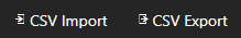
To define multiple tags use the CSV Export and CSV Import on the toolbar in the upper right together with Microsoft Excel.
NOTE: Tags can also be programmatically assigned with the OAS REST API or .NET Server Configuration interface.
Step 4 – Save GPIO Tags
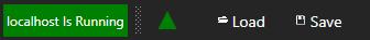
Select the Save button on the toolbar at the top.
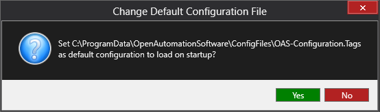
Enter a file name to be saved in C:\ProgramData\OpenAutomationSoftware\ConfigFiles directory on Windows or ConfigFiles subdirectory on Linux.
When prompted to set the file as the default configuration to load on startup select Yes.
The tags defined are now ready for use in all OAS features like Data Logging, Data Route, and Open UIEngine.