Troubleshooting – Modbus
How to identify and resolve communications errors with data sources.

- 0:00 - Introduction
- 0:40 - Bad Tags
- 3:30 - System Errors
- 4:20 - Watch Window
- 6:20 - Error Logging
- 7:20 - Troubleshooting Guides
- 8:55 - Contact Us
Below are some helpful troubleshooting steps to resolve bad data quality for tags with a Data Source of Modbus.
![]()
Master or Slave
To communicate to Modbus slave devices set the Type under Configure-Drivers to Master so OAS is a Modbus Master.
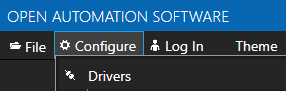
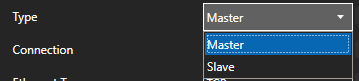
When the Type is set to Slave OAS can act as a Modbus slave for Modbus masters to read and write data from OAS.
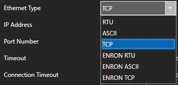
Protocol Type
The protocol type can be set to TCP, RTU, or ASCII. Although OAS can support all 3 protocols on either Ethernet or Serial interfaces it is typical to use TCP over Ethernet and RTU or ASCII over Serial.
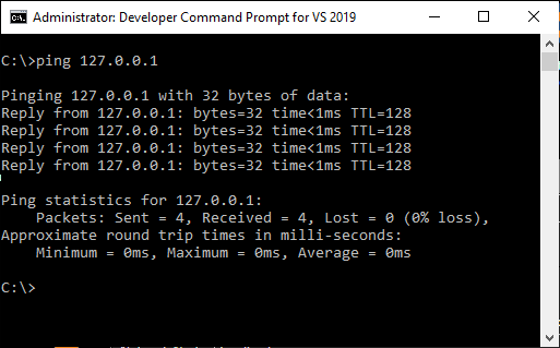
IP Address
When connecting to a Modbus slave over Ethernet the device will need to be reachable from the OAS system. Use Windows Command Prompt or Linux terminal where the OAS Engine is running to ping the device to verify it is reachable.
Memory Type
Specify the correct Memory Type for the data within the device.
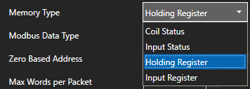
- Coil Status: 1 - 09999
- Input Status: 10001 - 19999
- Input Register: 30001 - 39999
- Holding Register: 40001 - 465535
Address
The Address field should not contain the base address of the memory type used.
![]()
For example to access holding register 40,001 set the Memory Type to Holding Register and the Address to 1.
Extended addressing is also supported. To communicate to 410001 set the Memory Type to Holding Register and the address to 10001.
Holding Register Address Range
- 40,001 use Address of 1
- 49,999 use Address of 9,999
- 50,000 use Address of 10,000
- 410,001 use Address of 10,001
- 420,000 use Address of 20,000
- 430,000 use Address of 30,000
- 440,000 use Address of 40,000
- 450,000 use Address of 50,000
- 460,000 use Address of 60,000
- 465,535 use Address of 65,535
Zero Based Addressing
Zero Based Addressing will subtract 1 from the address when communicating to the device.
![]()
Example: When communicating to Holding Register 40000 the Memory Type will be Holding Register and the Address would be 1.
Refer to the vendor's documentation if the device uses 0 base addressing or 1 base addressing.
Modbus Data Type
The Modbus Data Type for the tag should be set to the correct type based on the data to obtained from the controller.
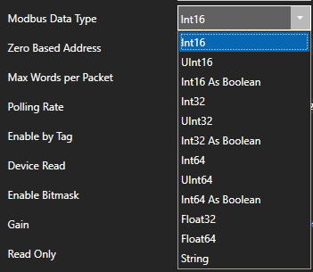
To access 4 byte single floats use Float32. To access 8 byte double floats use Float64.
To access individual bits of a Holding Register or Input Register use Int16 As Boolean, Int32 As Boolean, or Int64 As Boolean.
Also match the OAS tag Data Type to the correct value type to be set. If you are unsure of the data type use Object to see the result.
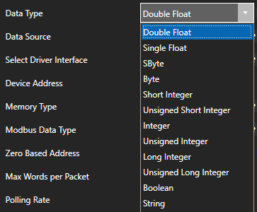
Note: If you are using Gain and Offset in a tag to scale an integer value to a floating point value use Double Float or Single Float as the Data Type.
One or More Invalid Addresses
If one or more of the Tags defined to the Driver Interface has invalid address defined or the address does not exist in the device the remaining good addresses can be affected with either taking the device offline or invalid packet request or response.
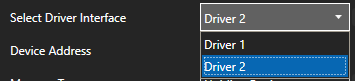
To isolate one or more tags to their own dedicated communication channel select the existing driver interface and change the name to a new unique name and select Add Driver.
![]()
To define a tag to the new driver select Configure-Tags, then select the tag you want to isolate to select the new driver interface.
Select Apply Changes.
![]()
If the data quality changes to good for the tag then resolve the other addresses in the tags defined to the first driver interface used.
![]()
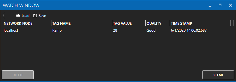
To help you further identify which tag addresses are bad use the Tag Watch Window to view multiple tags in one window.
To add a tag to the Watch Window, select any tag or tag group and right click on it. Then choose Add to Watch from the context menu.
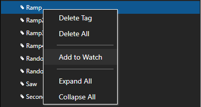
The tag you selected will then appear in the Watch Window.
Set Bad Msgs to Offline to 0 temporarily so the Driver Interface will remain online to continue to poll all addresses.
![]()
If an address is defined that does not exist in the device other tags with valid addresses can also be affected if the address is within range of the Max Words per Packet.
You can temporarily override packet optimization by adjusting the Max Words per Packet to 1 to poll each address independently in its own packet request. See Max Words per Packet following. Use Tag CSV Export and Import to set multiple tags with the same Max Words per Packet.
Once you identify which addresses are invalid investigate if the address exists in the device or refer to the vendor's documentation to find the correct addresses to use.
Max Words per Packet
Some Modbus devices have a limitation of packet size. Refer to the vendor's documentation as to what maximum packet size it can support. There are 2 bytes to each word, so if the device can support 250 bytes, the Max Words per Packet can be left at the default of 125.
![]()
The default value of Max Words per Packet is 125.
Note: Setting Max Words per Packet to a lower value can decrease the overall communication speed to the device. Use the highest possible the device supports for the best performance.
Word Swap and Byte Swap
Refer to the device vendor's documentation to determine if bytes or words need to be swapped to covert the raw integer values received and sent. If so use the properties Word Swap and / or Byte Swap.
![]()
Device Read Enabled
When the property Device Read is enabled polling communications will be disabled and read requests will only be performed when the tag defined for the Device Read transitions from false to true. If data is to be polled continuously from the device disable the tag property Device Read.
![]()
Enable by Tag
The Enable by Tag property is used to define a Boolean tag that will enable or disable communications for the tag. If data is to be polled continuously from the device disable the tag property Enable by Tag.
![]()
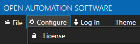
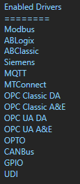
License
Use Configure-License to verify that the Driver Modbus is enabled.
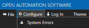
System Errors
Select Configure-System Errors and expand any Modbus or Driver Interface error to see the details of the error.
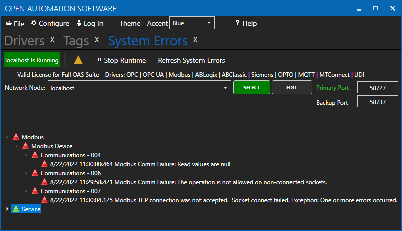
The information provided can often help you determine the cause of communication failures.
The history of all systems errors can be found in the OAS Error Log specified under Configure-Options-System Logging.
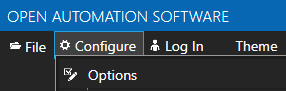
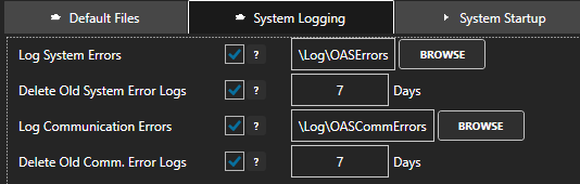
The default directory is the Log subdirectory in the OAS installation directory. On Windows the default location is C:\Program Files\Open Automation Software\OAS\Log\.
Example from log:
11:29:58.421 Modbus - Modbus Device - Communications - 006 - Modbus Comm Failure: The operation is not allowed on non-connected sockets.
11:30:00.464 Modbus - Modbus Device - Communications - 004 - Modbus Comm Failure: Read values are null
11:30:04.125 Modbus - Modbus Device - Communications - 007 - Modbus TCP connection was not accepted. Socket connect failed. Exception: One or more errors occurred.
Log Modbus Communications
You can enable the Modbus transaction logging under Configure-Options-System Logging to verify the device is responding to a request and analyze the packet optimization for each memory and address defined in the tag configuration.
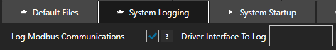
Optionally specify a specify a specific Driver Interface to capture with the property Driver Interface To Log or leave this blank to log all Modbus drivers.
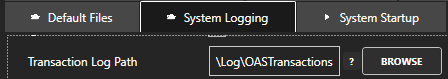
Specify the location of where the communication logs will be saved with the property Transaction Log Path further down in System Logging.
Following is an example from the log reading Holding Register 40001 with Zero Based Addressing.
12:10:12.944 ReadHoldingRegisters: Start Address: 0 Number of Points: 1
Wireshark
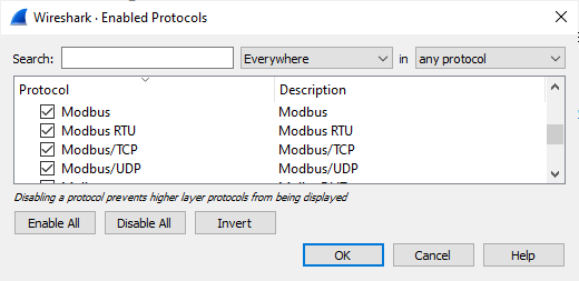
Wireshark is an excellent third party tool to analyze network communications over Ethernet. It has built in support for Modbus TCP and RTU protocols to convert the raw packets into easy to read Modbus protocol requests and responses. Select Analyze-Enabled Protocols to enable the Modbus protocols.
Use Apply a display filter field to filter the network traffic based on the IP address of the Modbus device you want to monitor with ip.addr == <IP address>, an example ip.addr == 192.168.0.1
You can download Wireshark from https://www.wireshark.org/download.html
ModScan32
ModScan32 is a good test application to communicate to Modbus devices to verify the device can respond to requests from the system.
You can download Modscan32 from WinTech Software Design.
Poor Network or Line Quality
If communication failures are intermittent due to weak radio signal or slow device response you can increase the Timeout and / or Number of Retries under Configure-Drivers.
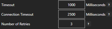
The default Timeout is 1000 milliseconds (1 second).
<< View All Troubleshooting Topics