How to Transfer Data from MQTT to Modbus
Open Automation Software can be used to transfer data from a MQTT broker to a Modbus device using Modbus TCP, Modbus RTU, and Modbus ASCII locally or over a network. This guide walks you through downloading and installing OAS, configuring a MQTT data source, a Modbus connector and one tag for each connector.
This guide uses the Data Route feature of OAS to transfer a Tag's value to another Tag's value using the Tag-to-Tag method.
For this guide on how to transfer data from a MQTT broker to a Modbus device you will need:
- To install MQTT Explorer or a similar tool for publishing messages to a MQTT broker and subscribing to messages in a MQTT broker
- A Modbus device or simulator connected to your workstation
See it in action
Talk to an OAS engineer about your specific configuration and see it in action
1 - Download and Install OAS
If you have not already done so, you will need to download and install the OAS platform.
Fully functional trial versions of the software are available for Windows, Windows IoT Core, Linux, Raspberry Pi and Docker on our downloads page.
On Windows, run the downloaded setup.exe file to install the Open Automation Software platform. For a default installation, Agree to the End User License Agreement and then click the Next button on each of the installation steps until it has completed.
If you'd like to customize your installation or learn more, use the following instructions:
The OAS Service Control application will appear when the installation finishes on Windows.
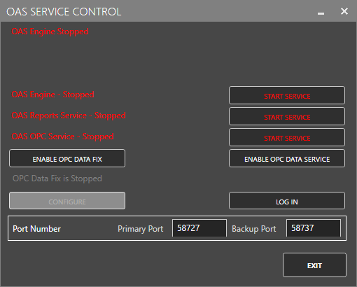
Click on each START SERVICE button to start each of the three OAS services.
2 - Configure OAS
Configure OAS is the main application used to configure local and remote OAS instances.
![]()
From your operating system start menu, open the Configure OAS application.
Select the Configure > Tags screen.
Important
If this is the first time you have installed OAS, the AdminCreate utility will run when you select a screen in the Configure menu. This will ask you to create a username and password for the admin user. This user will have full permissions in the OAS platform.
For further information see Getting Started - Security.
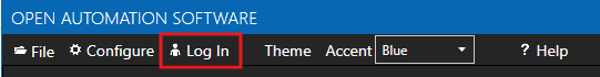
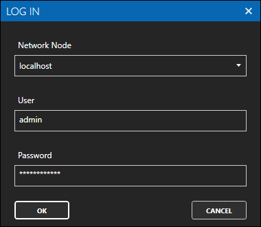
If this is the first time you are logging in, you will see the AdminCreate utility. Follow the prompts to set up your admin account. Otherwise, select the Log In menu button and provide the Network Node, username and password.
Info
In this guide you will use the Configure OAS application to configure the local Network Node which by default is localhost.
If you have installed OAS on a remote instance you can also connect to the remote instance by setting the relevant IP address or host name in the Network Node field.
3 - Configure MQTT Data Source Connector
In the following steps you will create and configure a MQTT Connector to connect to a third party broker so that tags will be able to subscribe to a topic. For the purposes of this guide, you will connect to the public HiveMQ broker.
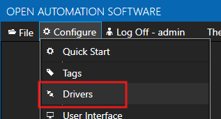
Select Configure > Drivers from the top menu.
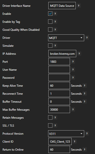
Enter a meaningful Driver Interface Name to give this driver interface instance a unique name.
Ensure the following parameters are configured:
- Driver: MQTT
- IP Address: broker.hivemq.com
- Port: 1883
- Client ID: OAS_Client_123
Tips
If you are having trouble reading a value in later steps, try to change the Client ID to something else as each client ID connecting to the broker must be unique.
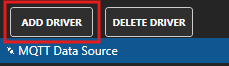
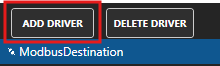
Click on the ADD DRIVER button on the left hand side to add this driver configuration. Once added, the driver interface name should appear in the list of drivers.
4 - Add Tags
In this step you will add two tags. One tag to represent a JSON payload coming from an external data source and a second Tag to represent the sensor value.
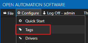
Select Configure > Tags from the top menu.
If you want to add a Tag to the root Tags group make sure the Tags node is selected in the tag list and click on the ADD TAG button.
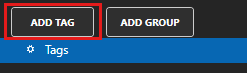
If you want to add a Tag to a Tag Group, select the Tag Group first and then click on the ADD TAG button.
You can also add Tag Groups by using the ADD GROUP button.
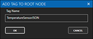
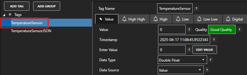
Enter TemperatureSensorJSON as the Tag name and click the OK button.
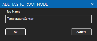
Repeat the above two steps and add another Tag with the name TemperatureSensor.
5 - Assign MQTT as Tag Data Source
You will now set the Tag's data source to the MQTT driver interface that you created previously.
At the end of this section you will need to use a tool like MQTT Explorer to publish a value to your Tag.
Select the Tag that will source data from the MQTT data source.
Set the following properties:
- Data Type: JSON
- Data Source: MQTT
- Select Driver Interface: MQTT Data Source
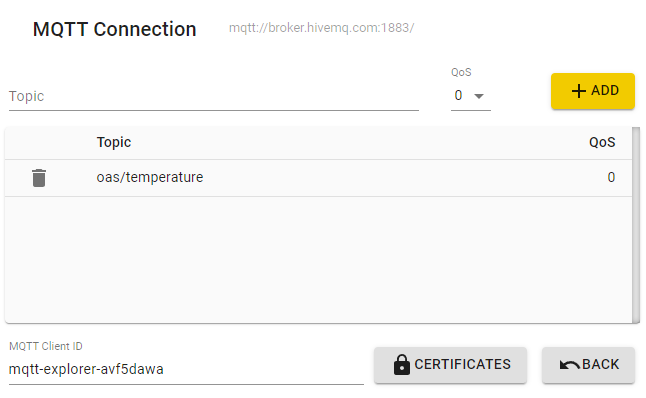
- Topic: oas/temperature
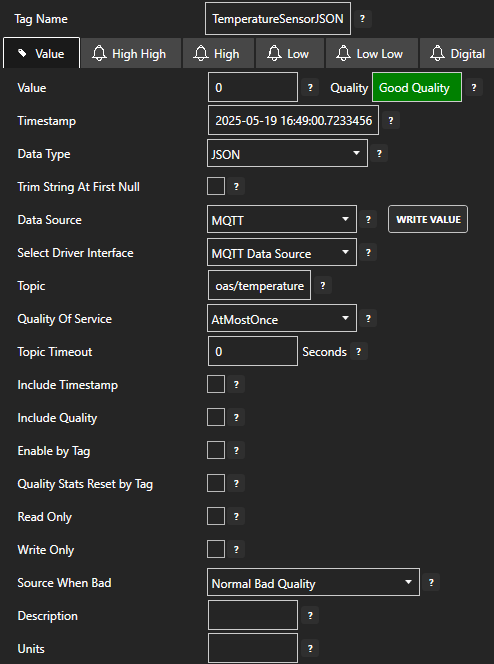
Click on the Apply Changes button to apply the changes.
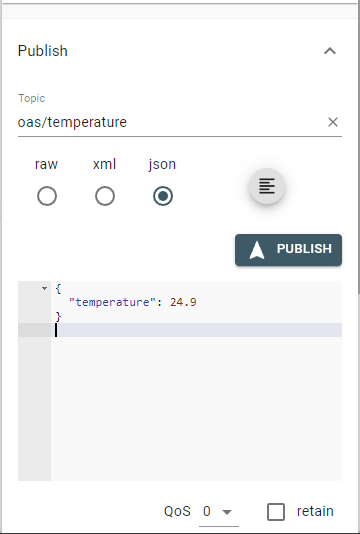
Using an MQTT testing tool to publish messages, such as MQTT Explorer, publish a JSON message to the oas/temperature topic.
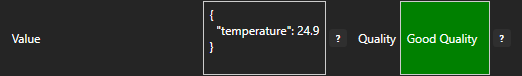
{
    "temperature": 24.9
}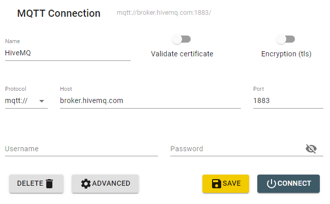
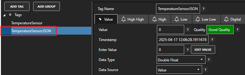
Check that the quality status is Good Quality and you can see the JSON value.
6 - Parse JSON Payload
In this step you will extract the sensor value from the JSON payload using a Calculation Tag and JSON functions.
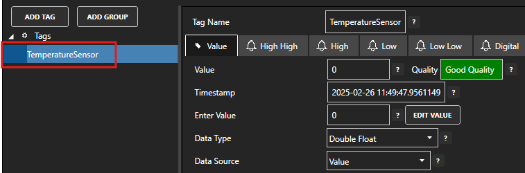
Select the Tag that will represent the temperature value.
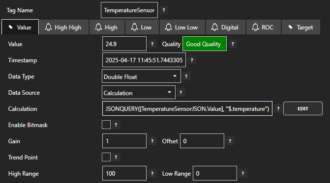
Set the Data Source value to Calculation.
Next to the Calculation field click on the EDIT button.
In the CALCULATION EDITOR window enter the following function.
JSONQUERY([TemperatureSensorJSON.Value], "$.temperature")This will extract the temperature field from the TemperatureSensorJSON Tag value.
Click the OK button to save the calculation.
Click on the Apply Changes button to apply the changes.
You should now see the sensor value in the Value field.
Tips
In this guide we used a separate calculation Tag in order to extract the sensor value. This is good practice when you want each Tag to have a single purpose and when you want to use the sensor value for other purposes like alarm thresholds and trending.
There is an alternative method using direct JSON access using the JSON property of a Tag. Instead of creating a separate TemperatureSensor calculation tag, the TemperatureSensorJSON tag can be accessed directly using the following syntax:
TemperatureJSON.JSON-temperature
This avoids having to create separate tags for each JSON property that you want to extract.
For more information on JSON handing, calculation and data access see the following:
7 - Configure Modbus Data Destination
In the following steps you will create and configure a Modbus Connector to act as a data destination. This will use a Master connection type and an Ethernet TCP connection. It assumes that your device is using the default port 502.
Select Configure > Drivers from the top menu.
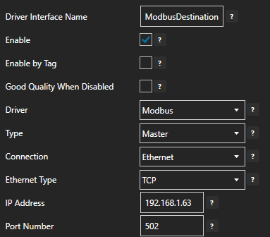
Enter a meaningful Driver Interface Name to give this driver interface instance a unique name.
Ensure the following parameters are configured:
- Driver: Modbus
- Type: Master
- Connection: Ethernet
- Ethernet Type: TCP
- Port: 502
Specify the device IP in the IP Address field.
Click on the ADD DRIVER button on the left hand side to add this driver configuration. Once added, the driver interface name should appear in the list of drivers.
8 - Add Data Destination Tag
In this section you will create a Tag to represent a data point that you want to write to.
Select Configure > Tags from the top menu.
If you want to add a Tag to the root Tags group make sure the Tags node is selected in the tag list and click on the ADD TAG button.
If you want to add a Tag to a Tag Group, select the Tag Group first and then click on the ADD TAG button.
You can also add Tag Groups by using the ADD GROUP button.
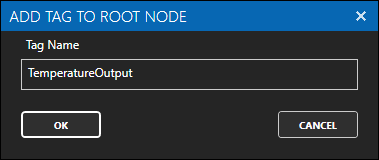
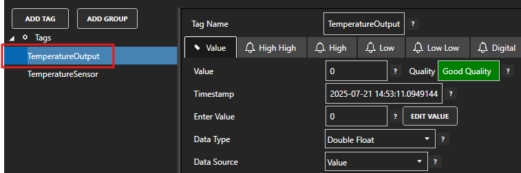
Provide a Tag Name such as TemperatureOutput and click the OK button.
9 - Assign Modbus as Tag Data Destination
You will now set the Tag's data source to the Modbus driver interface that you created previously to act as a data destination.
Select the Tag that will be associated with the Modbus destination.
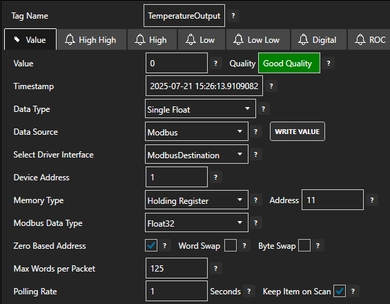
Set the Data Source to Modbus.
Set the Select Driver Interface drop-down to the ModbusDestination interface created previously.
Configure the Modbus parameters accordingly based on your device requirements.
- Device Address: The Modbus station number [default: 1]
- Memory Type: The Modbus data model table type [Coil Status, Input Status, Input Register, Holding Register]
- Address: The register to read/write based on the address offset
- Modbus Data Type: The Input and Holding Register data type
- Zero Based Address: Whether the Address starts at 0 or 1 [default: true]
- Word Swap & Byte Swap: Adjust as required for your controller type [default: false]
Set the polling rate in seconds by setting the Polling Rate property [default: 1 second].
Click on the Apply Changes button to apply the changes.
Check that the quality status is Good Quality and the data in the Value field is as expected. If the PLC does not hold any value in the given register then the value will remain zero.
10 - Configure Tag-To-Tag Data Route
In this section you will configure the Target of the source Tag to be the destination Tag value. This means whenever the source Tag value is updated, the destination Tag value will also be updated. This will cause a write operation on any associated driver if it is supported.
Select the source data Tag.
Select the Target tab.
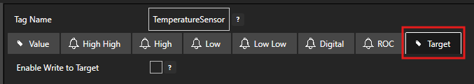
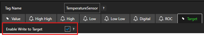
Enable the Enable Write to Target option.
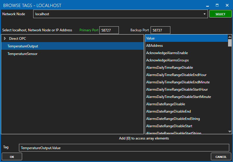
Click on the BROWSE button to select the destination tag.
Optionally, configure the Deadband property or enable Write Continuously to configure a continuous writing frequency.
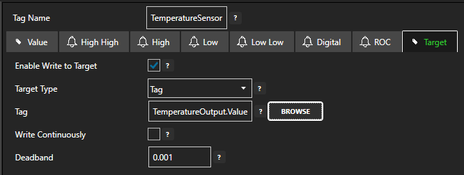
Click on the Apply Changes button to apply the configuration.
To verify that your data transfer is working correctly, select the destination Tag and check that the Tag value matches the Tag value of the source Tag.

You should also verify that the Tag value has been written to your destination device. Depending on your configuration in step 5 above, this destination value should be updated whenever the source value changes or at the given frequency.
11 - Modbus Troubleshooting
- Check your device address and register address and if the device is using Zero Based Addressing.
- Ensure the data types for the Tag and the Modbus Data Type match and if they are boolean or numeric values.
- Check your IP addresses and ports and any firewalls that might be enabled in the operating system.
- Enable Log Modbus Communications in the Configure > Options > System Logging screen and check the log files for any errors.
- Use tools such as Wire Shark to troubleshoot deeper connection and protocol issues.
12 - Save Changes
Once you have successfully configured your OAS instances, make sure you save your configuration.
On each configuration page, click on the Save button.
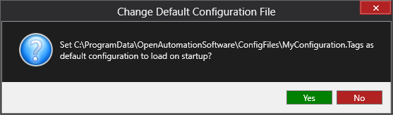
If this is the first time you are saving the configuration, or if you are changing the name of the configuration file, OAS will ask you if you want to change the default configuration file.
If you select Yes then OAS will make this configuration file the default and if the OAS service is restarted then this file will be loaded on start-up.
If you select No then OAS will still save your configuration file, but it will not be the default file that is loaded on start-up.
Important
Each configuration screen has an independent configuration file except for the Tags and Drivers configurations, which share the same configuration file. It is still important to click on the Save button whenever you make any changes.
For more information see: Save and Load Configuration
Info
- On Windows the configuration files are stored in C:\ProgramData\OpenAutomationSoftware\ConfigFiles.
- On Linux the configuration files are stored in the ConfigFiles subfolder of the OAS installation path.
Ready to get started?
Talk to an OAS engineer about your specific configuration and see it in action