Tag Variable Access
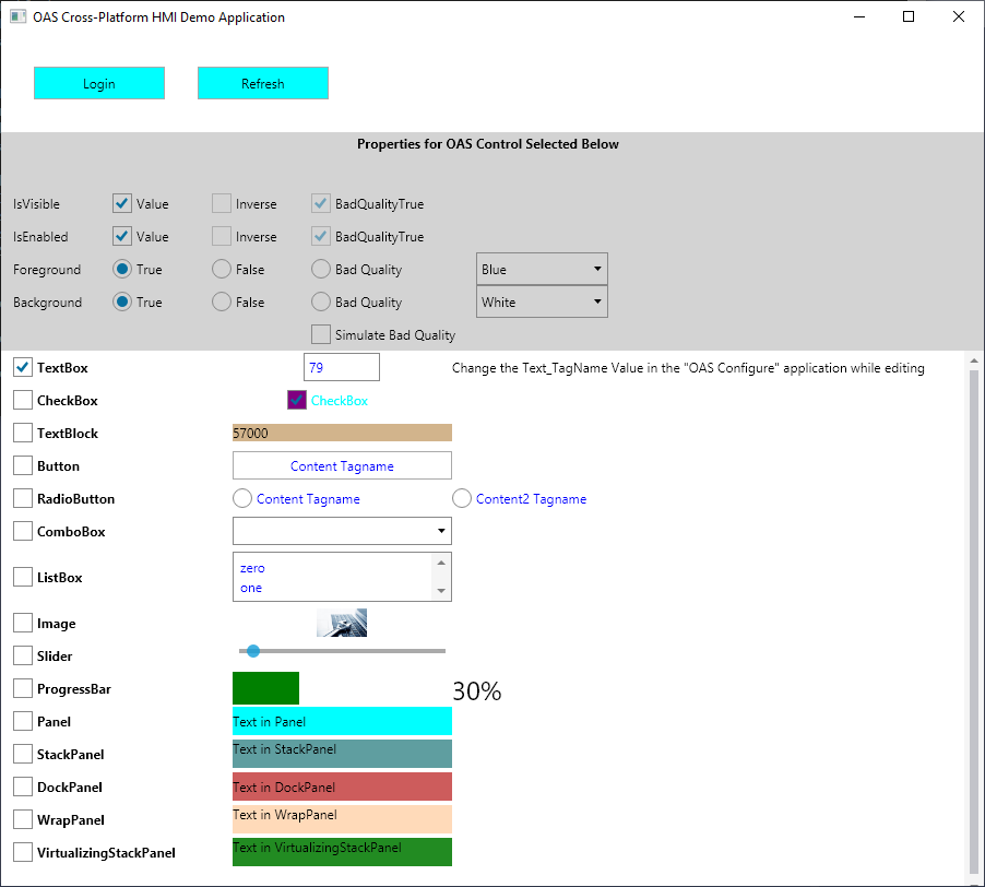
OAS client and OAS Engine interfaces can access all live data and configuration properties of a tag. Client applications would include WPF HMI, WinForm HMI, Cross-Platform HMI, and Web HMI user interfaces, OAS Excel Connector, and programmatic access through .NET Data Connector and REST API.
OAS Engine features that utilize tag variable access include Data Logging, Recipes, Calculation Tags, and Data Route Target Tags.
Tag Licensing
All variables can be accessed to each tag count as just one tag towards the OAS license. The exception would be access to bits of an integer tag and elements of an array tag which are counted as additional tags for licensing.
Tag Syntax
Value is the most commonly used variable of a Tag. Following is a list of all accessible variables from a tag. When browsing an OAS Tag from a client interface you will see all of the possible variable for selection.
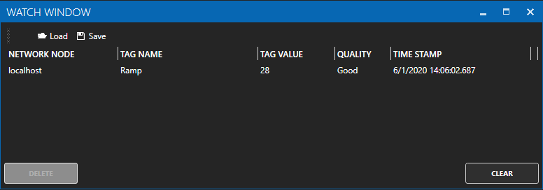
The OAS Excel browse application is a simple client to browse any tag for any available variable for a local or remote tag.
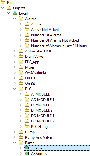
The following would be the full path for a local tag within a group.
myGroup.myTag.Value
Refer to Basic Networking or Live Data Cloud Networking for complete syntax for remote tag access.
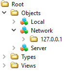
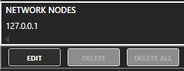
Basic Networking
\\192.168.0.1\myGroup.myTag.Value
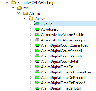
Live Data Cloud Networking from local OAS Engine
RemoteSCADAHosting.myLiveDataCloudNode.myGroup.myTag.Value
Live Data Cloud Networking though remote OAS Engine
\\192.168.0.1\RemoteSCADAHosting.myLiveDataCloudNode.myGroup.myTag.Value
The following is an example of accessing an element of an array as a read only variable.
myGroup.myTag.Value[0]
Variables
| Variable | Description |
|---|---|
| Value | The current value of the Tag. |
| Bit00-Bit15 | Individual bit of Value when Data Type is 16 bit, 32 bit, or 64 bit integer. |
| Bit16-Bit31 | Individual bit of Value when Data Type is 32 bit or 64 bit integer. |
| Bit32-Bit63 | Individual bit of Value when Data Type is 64 bit integer. |
| ABAddress | Configuration property: The Allen Bradley variable address. |
| AcknowledgeAlarmsEnable | Configuration property: Enable this feature to automatically acknowledge all alarms defined to the alarm groups defined in the property Alarm Groups to Acknowledge. The alarms are acknowledged when the Tag Value transitions from False to True. If the Tag Value remains True no further acknowledge will occur until the value goes to False and then True again. If you desire to acknowledge all alarms in the local service leave the Alarm Groups to Acknowledge field blank. |
| AcknowledgeAlarmsGroups | Configuration property: When the Acknowledge Alarm Groups property is enabled this is the list of Alarm Groups that will determine which alarms will be acknowledged automatically when the Tag Value transitions from False to True. If you desire to acknowledge all alarms in the local service leave this field blank. |
| AlarmsDailyTimeRangeDisable | Configuration property: Disable the alarms for the tag daily between the Start Hour and Minute and the End Hour and Minute. |
| AlarmsDailyTimeRangeDisableEndHour | Configuration property: The hour to end disabling the alarms daily. |
| AlarmsDailyTimeRangeDisableEndMinute | Configuration property: The minute to end disabling the alarms daily. |
| AlarmsDailyTimeRangeDisableStartHour | Configuration property: The hour to start disabling the alarms daily. |
| AlarmsDailyTimeRangeDisableStartMinute | Configuration property: The minute to start disabling the alarms daily. |
| AlarmsDateRangeDisable | Configuration property: Disable the alarms for the tag between a Start date and End date. |
| AlarmsDateRangeDisableEnd | Configuration property: The date to end disabling the alarms between a Start and End date. |
| AlarmsDateRangeDisableEndString | Configuration property: The date as a string to end disabling the alarms between a Start and End date. |
| AlarmsDateRangeDisableStart | Configuration property: The date to start disabling the alarms between a Start and End date. |
| AlarmsDateRangeDisableStartString | Configuration property: The date as a string to start disabling the alarms between a Start and End date. |
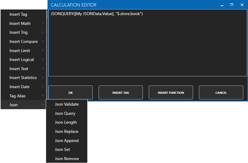
| Calculation | Configuration property: The equation when the Data Source is set to Calculation. See Getting Started with Calculations for descriptions of all functions. |
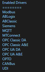
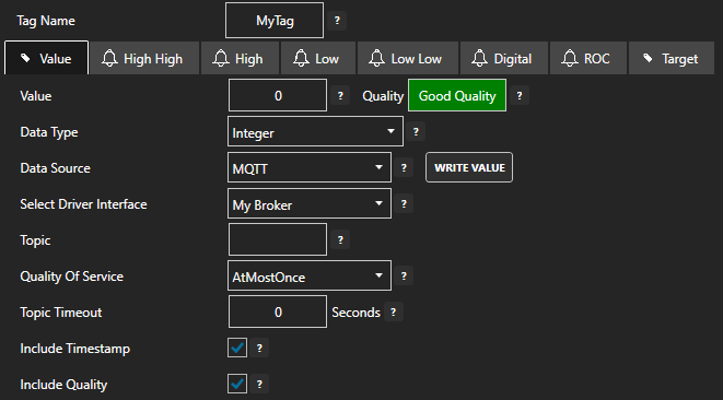
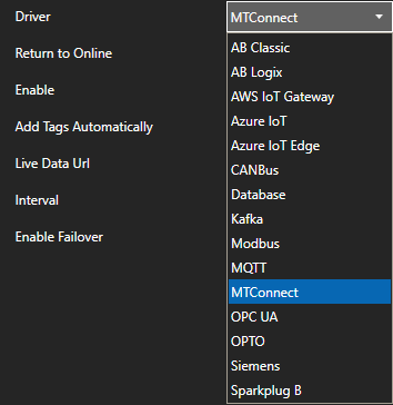
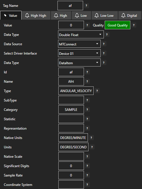
| DataSource | Configuration property: The source Of where the value will come from. The Data Source can be Set To one
Of the following types: Value: Fixed value that can be set in configuration or from any client. AB Classic: Communications to Allen Bradley MicroLogix, SLC 500, and PLC-5. AB Logix: Communications to Allen Bradley ControlLogix, CompactLogix, GuardLogix, and Micro800. AWS IoT Gateway: Amazon Web Services IoT Gateway. Azure IoT: Azure IoT Data Hub. Calculation: Math equation with multiple tag parameters as a data source. The result is read only and cannot be written to. View the following video to see how to define a Calculation. CANBus: CanBus interface FileBinary: Reads value from binary file with the file name of the full tag path And parameter name And extension .bin located in the directory specified in the File Data Source Path parameter under Configure-Options. When value is written to Tag the file will be updated with New value. FileText: Reads value from text file with the file name of the full tag path And parameter name And extension .txt located in the directory specified in the File Data Source Path parameter under Configure-Options. When value is written to Tag the file will be updated with New value. FileXML: Reads value from xml file With the file name Of the full tag path And parameter name And extension .xml located In the directory specified In the File Data Source Path parameter under Configure-Options. When value is written To Tag the file will be updated With New value. GPIO: Raspberry Pi General Purpose Input and Output pins. Modbus: Modbus master communications for Modbus TCP, Modbus RTU, and Modbus ASCII all supported on both Ethernet and Serial interfaces. MQTT: Communications to MQTT brokers to send and receive data to MQTT devices and software. MTConnect: Automated tag creation and live value update from MTConnect. OPC: Value from Classic DA 2.XX or 3.0 OPC Server. OPC UA: OPC UA Server. Siemens: Communications to Siemens S7-200, S7-300, S7-400, S7-1200, and S7-1500. Simulation: Dynamic simulation of data. Tag: Value is from another tag parameter from the same service or remote service. The result is read only and cannot be written to. Year: The current year as an Integer. Value is read only. Month: The current month as an Integer. Value is read only. Day: The current day as an Integer. Value is read only. Hour: The current hour as an Integer. Value is read only. Minute: The current minute as an Integer. Value is read only. Second: The current second as an Integer. Value is read only. Seconds Today: The total number of seconds elapsed in the current day as an Integer. Value is read only. Weekday: The current weekday As an Integer. Value is read only. 0 = Sunday, 1 = Monday, 2 = Tuesday, 3 = Wednesday, 4 = Thursday, 5 = Friday, 6 = Saturday. Weekday Name: The current weekday as a String. Value is read only. Date Time String: The current date And time as a String. Value is read only. UTC Year: The current Universal Time Code year as an Integer. Value is read only. UTC Month: The current Universal Time Code month as an Integer. Value is read only. UTC Day: The current Universal Time Code day as an Integer. Value is read only. UTC Hour: The current Universal Time Code hour as an Integer. Value is read only. UTC Minute: The current Universal Time Code minute as an Integer. Value is read only. UTC Second: The current Universal Time Code second as an Integer. Value is read only. UTC Seconds Today: The total number of seconds elapsed in the current Universal Time Code day as an Integer. Value is read only. UTC Weekday: The current Universal Time Code weekday As an Integer. Value is read only. 0 = Sunday, 1 = Monday, 2 = Tuesday, 3 = Wednesday, 4 = Thursday, 5 = Friday, 6 = Saturday. UTC Weekday Name: The current Universal Time Code weekday as a String. Value is read only. UTC Date Time String: The current Universal Time Code Date And time As a String. Value is read only. UDP Client Tag: Tag from a remote service with the UDP Broadcast feature enabled. Univeral Driver Interfaces will also appear here in the Data Source property |
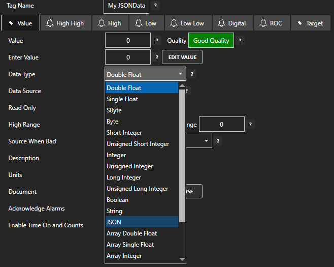
| DataType | Configuration property: The data type of a Parameter can be set to one of the following
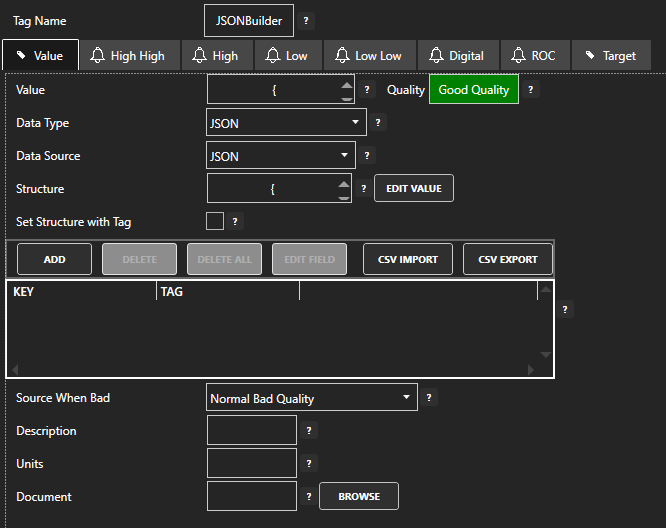
types. DoubleFloat (64 bits) SingleFloat (32 bits) SByteInteger (8 bits) ByteInteger (8 bits) ShortInteger (16 bits) UShortInteger (16 bits) IntegerNumber (32 bits) UIntegerNumber (32 bits) LongInteger (64 bits) ULongInteger (64 bits) LogicalDiscrete TextString JSON ArrayDouble (64 bits) ArraySingle (32 bits) ArrayInteger (32 bits) ArrayByte (8 bits) ArrayBoolean ArrayString ObjectType (Any value, custom Object, array, Or Structure) |
| DefaultValueDataTypeWhenBad | Configuration property: The data type to use when the Source When Bad is set to Set Sources to Default Value. See Source When Bad for full description. |
| DefaultValueWhenBad | Configuration property: The value to use when the Source When Bad is set to Set Sources to Default Value. See Source When Bad for full description. |
| Description | Configuration property: Description of the Tag used as the default Trend Pen Description. |
| Document | Configuration property: The document path that is included in an alarm message. |
| Gain | Configuration property: The Gain is a multiplier to the raw incoming value except when the Data Source
is Value: Value = RawValue * Gain + Offset When writing to an item the calculation is reversed: OutputValue = (Value – Offset) / Gain |
| HighRange | Configuration property: The Default Y Axis Range High For a trend pen and the high limit when Limit Writes is enabled. |
| IsReadOnly | Configuration property: When enabled the value of the parameter cannot be written to. |
| IsWriteOnly | Configuration property: When enabled the value of the parameter will not be read from the source but will allow writes. |
| JSON-KeyName | To access any individual element of a OAS tag with a Data Source of JSON use .JSON- |
| LimitWrites | Configuration property: Limit writes from users and clients within the High Range and Low Range. |
| LowRange | Configuration property: The Default Y Axis Range Low For a trend pen and the low limit when Limit Writes is enabled. |
| Offset | Configuration property: The Offset is an addition to the raw incoming value except when the Data Source
is Value: Value = RawValue * Gain + Offset When writing to an item the calculation is reversed: OutputValue = (Value – Offset) / Gain |
| OneOrMoreAlarmsDisabled | Read only: One or more alarm limits within the tag are disabled being inside of the daily time or data range to disable the limit. |
| OneOrMoreAlarmsPotentiallyDisabled | Read only: One or more of the alarm limits can be potentially disabled with daily or time range disable sepcified. |
| OPCDeviceRead | Configuration property: When enabled the Tag defined For the Device Read will control communications To only read the OPC Item With a SyncRead When the tag transitions from False To True. Normal asynchronous communications is disabled If this Property is enabled. |
| OPCDeviceReadTag | Configuration property: The Tag that will cause a syncread To the OPC Item When the value transitions from False To True. |
| OPCEnumerate | Configuration property: When enabled it will convert the integer value to the text from the item within the enumeration. |
| OPCEnumerateStrings | Configuration property: The list of enumerations to return based on integer value for the index. The string arrays are separated by a pipe character | |
| OPCItem | Configuration property: The OPC Item from a classic OPC DA Server. |
| OPCItemKeepOnScan | Configuration property: With this Option selected the communications To the OPC Item will always be
enabled unless the Device Read Option is selected. When this Option is disabled communications To the OPC Item will be enabled only When one Or more clients are requesting the value from the Tag. If the point is trended, enabled For alarm monitoring With any one Of the alarm limits enabled, Or Set As a Target output To another OPC Item this OPC Item will always be On scan regardless If there is a requesting client. Note: Not recommended for OPC Items from RS-Linx OPC Server as it does not handle dynamic adding and removing items well. |
| OPCQuality | Read only: The integer quality of the value when the Data Source is set to a Classic OPC Server. Typical value is 192 when the data quality is good. |
| OPCUpdateRate | Configuration property: OPC Update Rate for classic OPC Server item. Each unique rate creates an individual Group In the Server For subscription |
| OverrideOPCQualityWhenBad | Configuration property: Forces the OPC Quality that is passed onto the OPC Systems.NET OPC Server to good quality when the Data Source When Bad Quality is set to something other than the default of Normal Bad Quality and the Data Source is set to an OPC Item. |
| PreviousTimestamp | Read only: The timestamp of the previous value returned as a Date. |
| PreviousTimestampString | Read only: The timestamp of the previous value returned as a String. |
| PreviousTimestampTicks | Read only: The timestamp of the previous value returned as a Long Integer in Ticks. |
| PreviousValue | Read only: The previous value. |
| Quality | Quality of value, true when good quality, false when bad quality. |
| QualityActual | Read only: Quality of value, true when good quality, false when bad quality. |
| Quality_BadCount | Read only: The number of times the quality of the tag has transitioned from good to bad. Can be reset to 0 when .ResetCountsAndTime is set to true. |
| Quality_BadReadCount | Read only: The number of communication reads from the device has failed for the tag. Can be reset to 0 when .ResetCountsAndTime is set to true. |
| Quality_BadTime | Read only: The time in seconds the quality of the tags has been bad. Can be reset to 0 when .ResetCountsAndTime is set to true. |
| Quality_BadWriteCount | Read only: The number of write failures to the device from the tag. Can be reset to 0 when .ResetCountsAndTime is set to true. |
| Quality_GoodCount | Read only: The number of times the quality of the tag has transitioned from bad to good. Can be reset to 0 when .ResetCountsAndTime is set to true. |
| Quality_GoodReadCount | Read only: The number of communication reads from the device has succeeded for the tag. Can be reset to 0 when .ResetCountsAndTime is set to true. |
| Quality_GoodTime | Read only: The time in seconds the quality of the tags has been good. Can be reset to 0 when .ResetCountsAndTime is set to true. |
| Quality_GoodWriteCount | Read only: The number of successful writes to the device from the tag. Can be reset to 0 when .ResetCountsAndTime is set to true. |
| Quality_ResetCountsAndTime | Write a value of true to reset Quality_BadCount, Quality_BadReadCount, Quality_BadTime, Quality_BadWriteCount, Quality_GoodCount, Quality_GoodReadCount, Quality_GoodTime, and Quality_GoodWriteCount. |
| ReadOnlyValue | Configuration property: When enabled the value of the parameter cannot be written to. |
| ResetTimeDelay | Configuration property: The amount Of time To delay the Reset a Boolean value When Reset Value To False Is enabled. |
| ResetValue | Configuration property: When enabled For a Boolean Tag a write Of False will be sent immediately When the value transitions from False To True. |
| SiemensAddress | Configuration property: The Siemens variable address. See Siemens Address Syntax for address syntax. |
| SimulationRate | Configuration property: The rate of value changing for Simulation data. |
| SimulationType | Configuration property: Ramp will incrment in value from 0 to 99. Sine will change value from -1 to 1 based on the time each 60 seconds. Random will result in a random number with a range of 0 to 99 Toggle will transition between true and false |
| SourceWhenBad | Configuration property: Allows the value and data quality to be overridden when the value quality is
bad. The following are the four (4) available options for Source When Bad: NormalBadQuality: When the data source is bad quality the result is bad quality. With Calculations any one of the source tags in the calculation being bad quality will cause the result to be bad quality. SetSourcesToDefaultValue: When the data source quality is bad the source value is overridden to be what is set as Default Value with the data type of Default Value Type. With Calculations that have multiple tag parameters as a source each individual tag value in the calculation will be set to the Default Value when its individual data quality is bad. This will result in the calculation performing the equation with the remaining actual values with tags with good quality and overriding the values for the tags that are bad quality. HoldSourcesToLastGoodValue: When the data sources quality changes to bad quality the last good value will be used as the data source. With Calculations that have multiple tag parameters as a source each individual tag value in the calculation will be held with its last good value when its individual data quality is bad. This will result in the calculation performing the equation with remaining actual values with tags with good quality and overriding the values for the tags that are bad quality with each individual tags last good quality. SetSourcesToTagValue: When the data sources quality is bad the value from another Tag will be used. With Calculations that have multiple tag parameters as a source each individual tag value in the calculation will be set from the other Tag value. This will result in the calculation performing the equation with remaining actual values with tags with good quality and overriding the values for the tags that are bad quality with the assigned tag’s value. |
| Tag | Configuration property: Specify a local or remote Tag to receive the value from when the Data Source is set to Tag. |
| TagID | Configuration property: Internal variable used for programmatic access to identify tag. Can be set to any string value for custom identifier. |
| TagName | Configuration property: The Tag Name Is used To identify the specific point And all Of its parameters.
The Tag can be included within a Group. For example the following would be the full path For a Tag within a Group: – myGroup.myTag – The client applications will reference the tag name and parameter by name. – myGroup.myTag.Value or myGroup.myTag.ValueTimeOn. |
| TagNameWithoutGroups | Read only: The Tag Name without the parent group names included. |
| TargetEnable | Configuration property: Enables the Data Route feature to send the Tag Value to another Tag, OPC Item,
or Azure IoT. This feature Is Not required To just write To a Data Source Of the Tag Value from a client application. If the Data Source Of a Tag Is Set To something other than Value, Calculation, Tag, or Time and write occurs to the Tag the Data Source will be written to. The Target feature is mainly used to transfer values from controller to controller, OPC Servers to other OPC Servers, Calculation results to controllers, OPC Servers, or Azure IoT. Often used for remote data transfer over the Internet from Data Source to Data Destination. |
| TargetFloatDeadband | Configuration property: For floating point values this is the amount to compare with current value from target value and if within range it does not write a new value. If the source Value is different than the current Target value by more than the Float Deadband a write will occur. The deadband is not used if Write Continuously is enabled. |
| TargetOPCItem | Configuration property: The OPC Item from a classic OPC DA Server for sending the Value to. |
| TargetOPCUpdateRate | Configuration property: OPC Update Rate for classic OPC DA Item. |
| TargetWriteContinuously | Configuration property: When this property is disabled writes will only occur when the source Value is
different than the target value. When this property is enabled writes will continuously be performed at the rate of Target Write Continuously Frequency even if the source Value is the same as the target value. Note: When this feature is changed either the source Value must change or restart the service for the parameter to take effect. |
| TargetWriteContinuouslyFrequency | Configuration property: The rate at which the value is written to the destination if the continuous
writing is enabled. When this property is enabled writes will continuously be performed at the rate of Target Write Continuously Frequency. Note: When this feature is changed either the source Value must change or restart the service for the parameter to take effect. |
| TimeOnAndCountsEnable | Configuration property: When enabled it will keep track of how long a Boolean value is true and how many
times it transitions to True. The Time On And Counts feature will keep track of the following How Long the point is on for the current instance. How Long the point is on for the current day. How Long the point is on for Period 1. How Long the point is on for Period 2. How Long the point has been on for all of time. How many times the point has transitioned for the current day. How many times the point has transitioned for Period 1. How many times the point has transitioned for Period 2. How many times the point has transitioned For all of time. |
| TimeOnAndCountsDailyResetHour | Configuration property: The hour the Time On and Counts daily totals will be reset each day. |
| TimeOnAndCountsDailyResetMinute | Configuration property: The minute the Time On and Counts daily totals will be reset each day. |
| TimeOnAndCountsPeriod1 | Configuration property: The total time in minutes to track for Period 1 of Time On and Counts. |
| TimeOnAndCountsPeriod2 | Configuration property: The total time in minutes to track for Period 2 of Time On and Counts. |
| TimeOnAndCountsResetEnable | Configuration property: When enabled the Time On and Counts totals are reset when the Boolean Tag defined transistions from False to True. |
| TimeOnAndCountsResetTag | Configuration property: The Boolean Tag that will reset the Time On and Counts totals when its value transitions from False to True. |
| TimeOnUnits | Configuration property: The Time On values can be returned as Hours, Minutes, or Seconds. |
| Timestamp | Read only: The timestamp of the current value returned as a Date data type. |
| TimestampString | Read only: The timestamp of the current value returned as a string. |
| TimestampTicks | Read only: The timestamp of the current value returned in Ticks. |
| TimestampUNIX | Read only: The timestamp of the current value returned in UNIX Epoch. |
| TimestampPolled | Read only: The time when the Modbus Tag was last polled to obtain the current value returned as a Date data type. |
| TimestampPolledString | Read only: The time when the Modbus Tag was last polled to obtain the current value returned as a string. |
| TimestampPolledTicks | Read only: The time when the Modbus Tag was last polled to obtain the current value returned in Ticks. |
| TimestampPolledUNIX | Read only: The time when the Modbus Tag was last polled to obtain the current value returned in UNIX Epoch. |
| TrendPoint | Configuration property: Enable Trend Point To have the Parameter available for trending from Trend .NET and Web Trend. You can data log a Parameter value without trending the point If desired. |
| UDPClientTag | Configuration property: The Tag in the broadcasting service to receive the value when using one way UDP Broadcast feature. |
| Units | Configuration property: Engineering Units of the Tag used as the default Trend Pen Units. |
| WriteOnlyValue | Configuration property: When enabled the value of the parameter will not be read from the source but will allow writes. |
| ValueTimeOn | Read only: How Long the point is on for the current instance |
| ValueTimeOnCurrentDay | Read only: How Long the point is on for the current day. |
| ValueTimeOnPeriod1 | Read only: How Long the point is on for Period 1. |
| ValueTimeOnPeriod2 | Read only: How Long the point is on for Period 2. |
| ValueTimeOnTotal | Read only: How Long the point has been on for all of time. |
| ValueCountCurrentDay | Read only: How many times the point has transitioned for the current day. |
| ValueCountPeriod1 | Read only: How many times the point has transitioned for Period 1. |
| ValueCountPeriod2 | Read only: How many times the point has transitioned for Period 2. |
| ValueCountTotal | Read only: How many times the point has transitioned For all of time. |
| AlarmStatusHighHigh | Read only: The alarm state is active. |
| HighHighAlarmABAddress | Configuration property: The Allen Bradley variable address. |
| HighHighAlarmAcknowledge | Write only: Set to true to acknowledge alarm. |
| HighHighAlarmAcknowledged | Read only: True if alarm is currently acknowledged. |
| HighHighAlarmActive | Read only: The alarm state is active. |
| HighHighAlarmCalculation | Configuration property: The equation when the Data Source is set to Calculation. See Getting Started with Calculations for descriptions of all functions. |
| HighHighAlarmDailyTimeRangeDisable | Configuration property: Disable the alarm daily between the Start Hour and Minute and the End Hour and Minute. |
| HighHighAlarmDailyTimeRangeDisableEndHour | Configuration property: The hour to end disabling the alarm daily. |
| HighHighAlarmDailyTimeRangeDisableEndMinute | Configuration property: The minute to end disabling the alarm daily. |
| HighHighAlarmDailyTimeRangeDisableStartHour | Configuration property: The hour to start disabling the alarm daily. |
| HighHighAlarmDailyTimeRangeDisableStartMinute | Configuration property: The minute to start disabling the alarm daily. |
| HighHighAlarmDataSource | Configuration property: The source Of where the value will come from. The Data Source can be Set To one
Of the following types: Value: Fixed value that can be set in configuration or from any client. AB Classic: Communications to Allen Bradley MicroLogix, SLC 500, and PLC-5. AB Logix: Communications to Allen Bradley ControlLogix, CompactLogix, GuardLogix, and Micro800. AWS IoT Gateway: Amazon Web Services IoT Gateway. Azure IoT: Azure IoT Data Hub. Calculation: Math equation with multiple tag parameters as a data source. The result is read only and cannot be written to. View the following video to see how to define a Calculation. CANBus: CanBus interface FileBinary: Reads value from binary file with the file name of the full tag path And parameter name And extension .bin located in the directory specified in the File Data Source Path parameter under Configure-Options. When value is written to Tag the file will be updated with New value. FileText: Reads value from text file with the file name of the full tag path And parameter name And extension .txt located in the directory specified in the File Data Source Path parameter under Configure-Options. When value is written to Tag the file will be updated with New value. FileXML: Reads value from xml file With the file name Of the full tag path And parameter name And extension .xml located In the directory specified In the File Data Source Path parameter under Configure-Options. When value is written To Tag the file will be updated With New value. Modbus: Modbus master communications for Modbus TCP, Modbus RTU, and Modbus ASCII all supported on both Ethernet and Serial interfaces. MQTT: Communications to MQTT brokers to send and receive data to MQTT devices and software. MTConnect: Automated tag creation and live value update from MTConnect. OPC: Value from Classic DA 2.XX or 3.0 OPC Server. OPC UA: OPC UA Server. Siemens: Communications to Siemens S7-200, S7-300, S7-400, S7-1200, and S7-1500. Simulation: Dynamic simulation of data. Tag: Value is from another tag parameter from the same service or remote service. The result is read only and cannot be written to. Year: The current year as an Integer. Value is read only. Month: The current month as an Integer. Value is read only. Day: The current day as an Integer. Value is read only. Hour: The current hour as an Integer. Value is read only. Minute: The current minute as an Integer. Value is read only. Second: The current second as an Integer. Value is read only. Seconds Today: The total number of seconds elapsed in the current day as an Integer. Value is read only. Weekday: The current weekday As an Integer. Value is read only. 0 = Sunday, 1 = Monday, 2 = Tuesday, 3 = Wednesday, 4 = Thursday, 5 = Friday, 6 = Saturday. Weekday Name: The current weekday as a String. Value is read only. Date Time String: The current date And time as a String. Value is read only. UTC Year: The current Universal Time Code year as an Integer. Value is read only. UTC Month: The current Universal Time Code month as an Integer. Value is read only. UTC Day: The current Universal Time Code day as an Integer. Value is read only. UTC Hour: The current Universal Time Code hour as an Integer. Value is read only. UTC Minute: The current Universal Time Code minute as an Integer. Value is read only. UTC Second: The current Universal Time Code second as an Integer. Value is read only. UTC Seconds Today: The total number of seconds elapsed in the current Universal Time Code day as an Integer. Value is read only. UTC Weekday: The current Universal Time Code weekday As an Integer. Value is read only. 0 = Sunday, 1 = Monday, 2 = Tuesday, 3 = Wednesday, 4 = Thursday, 5 = Friday, 6 = Saturday. UTC Weekday Name: The current Universal Time Code weekday as a String. Value is read only. UTC Date Time String: The current Universal Time Code Date And time As a String. Value is read only. UDP Client Tag: Tag from a remote service with the UDP Broadcast feature enabled. Univeral Driver Interfaces will also appear here in the Data Source property |
| HighHighAlarmDateRangeDisable | Configuration property: Disable the alarm between a Start date and End date. |
| HighHighAlarmDateRangeDisableEnd | Configuration property: The date to end disabling the alarm between a Start and End date. |
| HighHighAlarmDateRangeDisableEndString | Configuration property: The date as a string to end disabling the alarm between a Start and End date. |
| HighHighAlarmDateRangeDisableStart | Configuration property: The date to start disabling the alarm between a Start and End date. |
| HighHighAlarmDateRangeDisableStartString | Configuration property: The date as a string to start disabling the alarm between a Start and End date. |
| HighHighAlarmDeadband | Configuration property: The amount that the value must be within the limit before the alarm condition is cleared. |
| HighHighAlarmDefaultValueDataTypeWhenBad | Configuration property: The data type to use when the Source When Bad is set to Set Sources to Default Value. See Source When Bad for full description. |
| HighHighAlarmDefaultValueWhenBad | Configuration property: The value to use when the Source When Bad is set to Set Sources to Default Value. See Source When Bad for full description. |
| HighHighAlarmDocument | Configuration property: The document path that is included in an alarm message. |
| HighHighAlarmDynamicAlarmText | Configuration property: The Alarm Text of an alarm message can be dynamic based on other Tag
values. The following options can be used for changing the Alarm Text Static Alarm Text: No change to the alarm text is performed, the default Alarm Text is used. Prepend Alarm Text: Adds the value of the dynamic alarm text tag ahead of the base Alarm Text. Overwrite Alarm Text: Replaces the alarm text entirely with the value of the dynamic alarm text tag. Append Alarm Text: Appends the value of the dynamic alarm text after the base Alarm Text. Calculation: The alarm text is replaced with the result of a Calculation. When the alarm occurs the current value of the alarm message is locked for that instance of the alarm so when it is acknowledged or it clears the message is the same for all states. |
| HighHighAlarmDynamicAlarmTextTag | Configuration property: The Tag that will contain the string value to update the alarm text. |
| HighHighAlarmEnable | Configuration property: Enable alarm limit. |
| HighHighAlarmEnableTag | Configuration property: Tag that will control when the alarm limit is enabled. |
| HighHighAlarmEnableWithTag | Configuration property: When enabled a Boolean Tag defined controls if the alarm limit is enabled. |
| HighHighAlarmGain | Configuration property: The Gain is a multiplier to the raw incoming value except when the Data Source
is Value: Value = RawValue * Gain + Offset When writing to an item the calculation is reversed: OutputValue = (Value – Offset) / Gain |
| HighHighAlarmGroup | Configuration property: Used in Alarm Logging, Alarm Notification, and .Net and Web Alarm interfaces for filtering alarms based on group. Simply enter the new alarm group or select from the existing list of groups. OPC, System, and Tag Client are default alarm groups used to identify system and communication alarms. |
| HighHighAlarmHighRange | Configuration property: The Default Y Axis Range High For a trend pen and the high limit when Limit Writes is enabled. |
| HighHighAlarmIsReadOnly | Configuration property: When enabled the AlarmLimit cannot be written to. |
| HighHighAlarmLatchEnable | Configuration property: When set to true each alarm instance will latch in the active state and will only return to normal when LatchReset is set to true after the alarm has returned to normal. |
| HighHighAlarmLatchReset | Write only: Resets a latched alarm when LatchEnable is used. |
| HighHighAlarmLimit | Configuration property: The value of the alarm limit. |
| HighHighAlarmLimitWrites | Configuration property: Limit writes from users and clients within the High Range and Low Range. |
| HighHighAlarmLogAsEvent | Configuration property: When the Value reaches the alarm limit the event will not be indicated and recorded as an alarm with acknowledge state, but instead as an event that just records the one instance of when it reaches the alarm limit. |
| HighHighAlarmLowRange | Configuration property: The Default Y Axis Range Low For a trend pen and the low limit when Limit Writes is enabled. |
| HighHighAlarmOffset | Configuration property: The Offset is an addition to the raw incoming value except when the Data Source
is Value: Value = RawValue * Gain + Offset When writing to an item the calculation is reversed: OutputValue = (Value – Offset) / Gain |
| HighHighAlarmOPCDeviceRead | Configuration property: When enabled the Tag defined For the Device Read will control communications To only read the OPC Item With a SyncRead When the tag transitions from False To True. Normal asynchronous communications is disabled If this Property is enabled. |
| HighHighAlarmOPCDeviceReadTag | Configuration property: The Tag that will cause a syncread To the OPC Item When the value transitions from False To True. |
| HighHighAlarmOPCItem | Configuration property: The OPC Item from a classic OPC DA Server. |
| HighHighAlarmOPCQuality | Configuration property: Read only: The integer quality of the value when the Data Source is set to a Classic OPC Server. Typical value is 192 when the data quality is good. |
| HighHighAlarmOPCUpdateRate | Configuration property: OPC Update Rate for classic OPC Server item. Each unique rate creates an individual Group In the Server For subscription |
| HighHighAlarmOverrideOPCQualityWhenBad | Configuration property: Forces the OPC Quality that is passed onto the OPC Systems.NET OPC Server to good quality when the Data Source When Bad Quality is set to something other than the default of Normal Bad Quality and the Data Source is set to an OPC Item. |
| HighHighAlarmPreviousTimestamp | Read only: The timestamp of the previous alarm limit returned as a Date. |
| HighHighAlarmPreviousTimestampString | Read only: The timestamp of the previous alarm limit returned as a String. |
| HighHighAlarmPreviousTimestampTicks | Read only: The timestamp of the previous alarm limit returned as a Long Integer in Ticks. |
| HighHighAlarmPreviousValue | Read only: The previoius alarm limit value. |
| HighHighAlarmPriority | Configuration property: Used in Alarm Logging, Alarm Notification, and .Net and Web Alarm interfaces for filtering alarms based on group. The valid range is from 0 to 2,147,483,647. |
| HighHighAlarmQuality | Quality of alarm limit value, true when good quality, false when bad quality. |
| HighHighAlarmQualityActual | Read only: Quality of alarm limit value, true when good quality, false when bad quality. |
| HighHighAlarmReadOnlyValue | Configuration property: When enabled the AlarmLimit cannot be written to. |
| HighHighAlarmSiemensAddress | Configuration property: The Siemens variable address. See Siemens Address Syntax for address syntax. |
| HighHighAlarmSimulationRate | Configuration property: The rate of alarm limit value changing for Simulation data. |
| HighHighAlarmSimulationType | Configuration property: Ramp will incrment in value from 0 to 99. Sine will change value from -1 to 1 based on the time each 60 seconds. Random will result in a random number with a range of 0 to 99 Toggle will transition between true and false |
| HighHighAlarmSourceWhenBad | Configuration property: Allows the alarm limit value and data quality to be overridden when the value
quality is bad. The following are the four (4) available options for Source When Bad: NormalBadQuality: When the data source is bad quality the result is bad quality. With Calculations any one of the source tags in the calculation being bad quality will cause the result to be bad quality. SetSourcesToDefaultValue: When the data source quality is bad the source value is overridden to be what is set as Default Value with the data type of Default Value Type. With Calculations that have multiple tag parameters as a source each individual tag value in the calculation will be set to the Default Value when its individual data quality is bad. This will result in the calculation performing the equation with the remaining actual values with tags with good quality and overriding the values for the tags that are bad quality. HoldSourcesToLastGoodValue: When the data sources quality changes to bad quality the last good value will be used as the data source. With Calculations that have multiple tag parameters as a source each individual tag value in the calculation will be held with its last good value when its individual data quality is bad. This will result in the calculation performing the equation with remaining actual values with tags with good quality and overriding the values for the tags that are bad quality with each individual tags last good quality. SetSourcesToTagValue: When the data sources quality is bad the value from another Tag will be used. With Calculations that have multiple tag parameters as a source each individual tag value in the calculation will be set from the other Tag value. This will result in the calculation performing the equation with remaining actual values with tags with good quality and overriding the values for the tags that are bad quality with the assigned tag’s value. |
| Tag | Configuration property: Specify a local Or remote Tag To receive the value from when the Data Source is set to Tag. |
| HighHighAlarmTag | Configuration property: Specify a local or remote Tag to receive the value from when the Data Source is set to Tag. |
| HighHighAlarmTagID | Configuration property: Internal variable used for programmatic access to identify tag. Can be set to any string value for custom identifier. |
| HighHighAlarmText | Configuration property: Alarm text to use for Alarm Logging, Alarm Notfication, and .NET and Web Alarm
interface. The Alarm Text can be fixed or dynamic with the Dynamic Alarm Text attribute. |
| HighHighAlarmTextValue | Read only: The current alarm text that would be used when the alarm transistions into the active state. |
| HighHighAlarmTimeDelay | Configuration property: The time delay in seconds that the alarm condition must remain active before the
alarm is posted as an active alarm. The date and time when the alarm first became active is used as the
alarm date and time, not the date and time it was posted as an active alarm. If you would Like the AlarmStatus parameter To be Set immediate And Not wait For the Time Delay use Configure-Options To Set Update Alarm Status Immediately without Alarm Time Delay. |
| HighHighAlarmTimeDelayRemaining | Read only: The time remaining in seconds if the tag value exceeds the alarm limit and is waiting the time delay to set the alarm as active. |
| HighHighAlarmTimeOnAndCountsEnable | Configuration property: When enabled it will keep track of how long the alarm is active and how many
times it transitions from inactive to active state. The Time On And Counts feature will keep track of the following How Long the alarm is active for the current instance. How Long the alarm is active for the current day. How Long the alarm is active for Period 1. How Long the alarm is active for Period 2. How Long the alarm is active for all of time. How many times the alarm state has transitioned from inactive to active for the current day. How many times the alarm state has transitioned from inactive to active for Period 1. How many times the alarm state has transitioned from inactive to active for Period 2. How many times the alarm state has transitioned from inactive to active For all of time. |
| HighHighAlarmTimeOnAndCountsDailyResetHour | Configuration property: The hour the Time On and Counts daily totals will be reset each day. |
| HighHighAlarmTimeOnAndCountsDailyResetMinute | Configuration property: The minute the Time On and Counts daily totals will be reset each day. |
| HighHighAlarmTimeOnAndCountsPeriod1 | Configuration property: The total time in minutes to track for Period 1 of Time On and Counts. |
| HighHighAlarmTimeOnAndCountsPeriod2 | Configuration property: The total time in minutes to track for Period 2 of Time On and Counts. |
| HighHighAlarmTimeOnAndCountsResetEnable | Configuration property: When enabled the Time On and Counts totals are reset when the Boolean Tag defined transistions from False to True. |
| HighHighAlarmTimeOnAndCountsResetTag | Configuration property: The Boolean Tag that will reset the Time On and Counts totals when its value transitions from False to True. |
| HighHighAlarmTimeOnUnits | Configuration property: The Time On values can be returned as Hours, Minutes, or Seconds. |
| HighHighAlarmTimestamp | Read only: The timestamp of the current alarm limit value returned as a Date data type. |
| HighHighAlarmTimeStampOffset | Configuration property: The amount of time to offset the alarm timestamp to match a particular time zone. If you prefer to use Universal Time Code enable the property Use UTC Timestamp under Configure-Options-Time. |
| HighHighAlarmTimestampString | Read only: The timestamp of the current alarm limit value returned as a string. |
| HighHighAlarmTimestampTicks | Read only: The timestamp of the current alarm limit value returned in Ticks. |
| HighHighAlarmTimestampUNIX | Read only: The timestamp of the current alarm limit value returned in UNIX Epoch. |
| HighHighAlarmTimestampPolled | Read only: The time when the Modbus value for the alarm limit was last polled to obtain the current value returned as a Date data type. |
| HighHighAlarmTimestampPolledString | Read only: The time when the Modbus value for the alarm limit was last polled to obtain the current value returned as a string. |
| HighHighAlarmTimestampPolledTicks | Read only: The time when the Modbus value for the alarm limit was last polled to obtain the current value returned in Ticks. |
| HighHighAlarmTimestampPolledUNIX | Read only: The time when the Modbus value for the alarm limit was last polled to obtain the current value returned in UNIX Epoch. |
| HighHighAlarmTrendPoint | Configuration property: Enable Trend Point To have the alarm limit, time on and counts, and alarm status available for trending from Trend .NET and Web Trend. You can data log a Parameter value without trending the point If desired. |
| HighHighAlarmUDPClientTag | Configuration property: The Tag in the broadcasting service to receive the value into the alarm limit when using one way UDP Broadcast feature. |
| HighHighAlarmUnits | Configuration property: Engineering Units that is included in the alarm message. |
| AlarmHighHighTimeOn | Read only: How Long the alarm is active for the current instance. |
| AlarmHighHighTimeOnCurrentDay | Read only: How Long the alarm is active for the current day. |
| AlarmHighHighTimeOnPeriod1 | Read only: How Long the alarm is active for Period 1. |
| AlarmHighHighTimeOnPeriod2 | Read only: How Long the alarm is active for Period 2. |
| AlarmHighHighTimeOnTotal | Read only: How Long the alarm is active for all of time. |
| AlarmHighHighCountCurrentDay | Read only: How many times the alarm state has transitioned from inactive to active for the current day. |
| AlarmHighHighCountPeriod1 | Read only: How many times the alarm state has transitioned from inactive to active for Period 1. |
| AlarmHighHighCountPeriod2 | Read only: How many times the alarm state has transitioned from inactive to active for Period 2. |
| AlarmHighHighCountTotal | Read only: How many times the alarm state has transitioned from inactive to active For all of time. |
| AlarmStatusHigh | Read only: The alarm state is active. |
| HighAlarmABAddress | Configuration property: The Allen Bradley variable address. |
| HighAlarmAcknowledge | Write only: Set to true to acknowledge alarm. |
| HighAlarmAcknowledged | Read only: True if alarm is currently acknowledged. |
| HighAlarmActive | Read only: The alarm state is active. |
| HighAlarmCalculation | Configuration property: The equation when the Data Source is set to Calculation. See Getting Started with Calculations for descriptions of all functions. |
| HighAlarmDailyTimeRangeDisable | Configuration property: Disable the alarm daily between the Start Hour and Minute and the End Hour and Minute. |
| HighAlarmDailyTimeRangeDisableEndHour | Configuration property: The hour to end disabling the alarm daily. |
| HighAlarmDailyTimeRangeDisableEndMinute | Configuration property: The minute to end disabling the alarm daily. |
| HighAlarmDailyTimeRangeDisableStartHour | Configuration property: The hour to start disabling the alarm daily. |
| HighAlarmDailyTimeRangeDisableStartMinute | Configuration property: The minute to start disabling the alarm daily. |
| HighAlarmDataSource | Configuration property: The source Of where the value will come from. The Data Source can be Set To one
Of the following types: Value: Fixed value that can be set in configuration or from any client. AB Classic: Communications to Allen Bradley MicroLogix, SLC 500, and PLC-5. AB Logix: Communications to Allen Bradley ControlLogix, CompactLogix, GuardLogix, and Micro800. AWS IoT Gateway: Amazon Web Services IoT Gateway. Azure IoT: Azure IoT Data Hub. Calculation: Math equation with multiple tag parameters as a data source. The result is read only and cannot be written to. View the following video to see how to define a Calculation. CANBus: CanBus interface FileBinary: Reads value from binary file with the file name of the full tag path And parameter name And extension .bin located in the directory specified in the File Data Source Path parameter under Configure-Options. When value is written to Tag the file will be updated with New value. FileText: Reads value from text file with the file name of the full tag path And parameter name And extension .txt located in the directory specified in the File Data Source Path parameter under Configure-Options. When value is written to Tag the file will be updated with New value. FileXML: Reads value from xml file With the file name Of the full tag path And parameter name And extension .xml located In the directory specified In the File Data Source Path parameter under Configure-Options. When value is written To Tag the file will be updated With New value. Modbus: Modbus master communications for Modbus TCP, Modbus RTU, and Modbus ASCII all supported on both Ethernet and Serial interfaces. MQTT: Communications to MQTT brokers to send and receive data to MQTT devices and software. MTConnect: Automated tag creation and live value update from MTConnect. OPC: Value from Classic DA 2.XX or 3.0 OPC Server. OPC UA: OPC UA Server. Siemens: Communications to Siemens S7-200, S7-300, S7-400, S7-1200, and S7-1500. Simulation: Dynamic simulation of data. Tag: Value is from another tag parameter from the same service or remote service. The result is read only and cannot be written to. Year: The current year as an Integer. Value is read only. Month: The current month as an Integer. Value is read only. Day: The current day as an Integer. Value is read only. Hour: The current hour as an Integer. Value is read only. Minute: The current minute as an Integer. Value is read only. Second: The current second as an Integer. Value is read only. Seconds Today: The total number of seconds elapsed in the current day as an Integer. Value is read only. Weekday: The current weekday As an Integer. Value is read only. 0 = Sunday, 1 = Monday, 2 = Tuesday, 3 = Wednesday, 4 = Thursday, 5 = Friday, 6 = Saturday. Weekday Name: The current weekday as a String. Value is read only. Date Time String: The current date And time as a String. Value is read only. UTC Year: The current Universal Time Code year as an Integer. Value is read only. UTC Month: The current Universal Time Code month as an Integer. Value is read only. UTC Day: The current Universal Time Code day as an Integer. Value is read only. UTC Hour: The current Universal Time Code hour as an Integer. Value is read only. UTC Minute: The current Universal Time Code minute as an Integer. Value is read only. UTC Second: The current Universal Time Code second as an Integer. Value is read only. UTC Seconds Today: The total number of seconds elapsed in the current Universal Time Code day as an Integer. Value is read only. UTC Weekday: The current Universal Time Code weekday As an Integer. Value is read only. 0 = Sunday, 1 = Monday, 2 = Tuesday, 3 = Wednesday, 4 = Thursday, 5 = Friday, 6 = Saturday. UTC Weekday Name: The current Universal Time Code weekday as a String. Value is read only. UTC Date Time String: The current Universal Time Code Date And time As a String. Value is read only. UDP Client Tag: Tag from a remote service with the UDP Broadcast feature enabled. Univeral Driver Interfaces will also appear here in the Data Source property |
| HighAlarmDateRangeDisable | Configuration property: Disable the alarm between a Start date and End date. |
| HighAlarmDateRangeDisableEnd | Configuration property: The date to end disabling the alarm between a Start and End date. |
| HighAlarmDateRangeDisableEndString | Configuration property: The date as a string to end disabling the alarm between a Start and End date. |
| HighAlarmDateRangeDisableStart | Configuration property: The date to start disabling the alarm between a Start and End date. |
| HighAlarmDateRangeDisableStartString | Configuration property: The date as a string to start disabling the alarm between a Start and End date. |
| HighAlarmDeadband | Configuration property: The amount that the value must be within the limit before the alarm condition is cleared. |
| HighAlarmDefaultValueDataTypeWhenBad | Configuration property: The data type to use when the Source When Bad is set to Set Sources to Default Value. See Source When Bad for full description. |
| HighAlarmDefaultValueWhenBad | Configuration property: The value to use when the Source When Bad is set to Set Sources to Default Value. See Source When Bad for full description. |
| HighAlarmDocument | Configuration property: The document path that is included in an alarm message. |
| HighAlarmDynamicAlarmText | Configuration property: The Alarm Text of an alarm message can be dynamic based on other Tag
values. The following options can be used for changing the Alarm Text Static Alarm Text: No change to the alarm text is performed, the default Alarm Text is used. Prepend Alarm Text: Adds the value of the dynamic alarm text tag ahead of the base Alarm Text. Overwrite Alarm Text: Replaces the alarm text entirely with the value of the dynamic alarm text tag. Append Alarm Text: Appends the value of the dynamic alarm text after the base Alarm Text. Calculation: The alarm text is replaced with the result of a Calculation. When the alarm occurs the current value of the alarm message is locked for that instance of the alarm so when it is acknowledged or it clears the message is the same for all states. |
| HighAlarmDynamicAlarmTextTag | Configuration property: The Tag that will contain the string value to update the alarm text. |
| HighAlarmEnable | Configuration property: Enable alarm limit. |
| HighAlarmEnableTag | Configuration property: Tag that will control when the alarm limit is enabled. |
| HighAlarmEnableWithTag | Configuration property: When enabled a Boolean Tag defined controls if the alarm limit is enabled. |
| HighAlarmGain | Configuration property: The Gain is a multiplier to the raw incoming value except when the Data Source
is Value: Value = RawValue * Gain + Offset When writing to an item the calculation is reversed: OutputValue = (Value – Offset) / Gain |
| HighAlarmGroup | Configuration property: Used in Alarm Logging, Alarm Notification, and .Net and Web Alarm interfaces for filtering alarms based on group. Simply enter the new alarm group or select from the existing list of groups. OPC, System, and Tag Client are default alarm groups used to identify system and communication alarms. |
| HighAlarmHighRange | Configuration property: The Default Y Axis Range High For a trend pen and the high limit when Limit Writes is enabled. |
| HighAlarmIsReadOnly | Configuration property: When enabled the AlarmLimit cannot be written to. |
| HighAlarmLatchEnable | Configuration property: When set to true each alarm instance will latch in the active state and will only return to normal when LatchReset is set to true after the alarm has returned to normal. |
| HighAlarmLatchReset | Write only: Resets a latched alarm when LatchEnable is used. |
| HighAlarmLimit | Configuration property: The value of the alarm limit. |
| HighAlarmLimitWrites | Configuration property: Limit writes from users and clients within the High Range and Low Range. |
| HighAlarmLogAsEvent | Configuration property: When the Value reaches the alarm limit the event will not be indicated and recorded as an alarm with acknowledge state, but instead as an event that just records the one instance of when it reaches the alarm limit. |
| HighAlarmLowRange | Configuration property: The Default Y Axis Range Low For a trend pen and the low limit when Limit Writes is enabled. |
| HighAlarmOffset | Configuration property: The Offset is an addition to the raw incoming value except when the Data Source
is Value: Value = RawValue * Gain + Offset When writing to an item the calculation is reversed: OutputValue = (Value – Offset) / Gain |
| HighAlarmOPCDeviceRead | Configuration property: When enabled the Tag defined For the Device Read will control communications To only read the OPC Item With a SyncRead When the tag transitions from False To True. Normal asynchronous communications is disabled If this Property is enabled. |
| HighAlarmOPCDeviceReadTag | Configuration property: The Tag that will cause a syncread To the OPC Item When the value transitions from False To True. |
| HighAlarmOPCItem | Configuration property: The OPC Item from a classic OPC DA Server. |
| HighAlarmOPCQuality | Configuration property: Read only: The integer quality of the value when the Data Source is set to a Classic OPC Server. Typical value is 192 when the data quality is good. |
| HighAlarmOPCUpdateRate | Configuration property: OPC Update Rate for classic OPC Server item. Each unique rate creates an individual Group In the Server For subscription |
| HighAlarmOverrideOPCQualityWhenBad | Configuration property: Forces the OPC Quality that is passed onto the OPC Systems.NET OPC Server to good quality when the Data Source When Bad Quality is set to something other than the default of Normal Bad Quality and the Data Source is set to an OPC Item. |
| HighAlarmPreviousTimestamp | Read only: The timestamp of the previous alarm limit returned as a Date. |
| HighAlarmPreviousTimestampString | Read only: The timestamp of the previous alarm limit returned as a String. |
| HighAlarmPreviousTimestampTicks | Read only: The timestamp of the previous alarm limit returned as a Long Integer in Ticks. |
| HighAlarmPreviousValue | Read only: The previoius alarm limit value. |
| HighAlarmPriority | Configuration property: Used in Alarm Logging, Alarm Notification, and .Net and Web Alarm interfaces for filtering alarms based on group. The valid range is from 0 to 2,147,483,647. |
| HighAlarmQuality | Quality of alarm limit value, true when good quality, false when bad quality. |
| HighAlarmQualityActual | Read only: Quality of alarm limit value, true when good quality, false when bad quality. |
| HighAlarmReadOnlyValue | Configuration property: When enabled the AlarmLimit cannot be written to. |
| HighAlarmSiemensAddress | Configuration property: The Siemens variable address. See Siemens Address Syntax for address syntax. |
| HighAlarmSimulationRate | Configuration property: The rate of alarm limit value changing for Simulation data. |
| HighAlarmSimulationType | Configuration property: Ramp will incrment in value from 0 to 99. Sine will change value from -1 to 1 based on the time each 60 seconds. Random will result in a random number with a range of 0 to 99 Toggle will transition between true and false |
| HighAlarmSourceWhenBad | Configuration property: Allows the alarm limit value and data quality to be overridden when the value
quality is bad. The following are the four (4) available options for Source When Bad: NormalBadQuality: When the data source is bad quality the result is bad quality. With Calculations any one of the source tags in the calculation being bad quality will cause the result to be bad quality. SetSourcesToDefaultValue: When the data source quality is bad the source value is overridden to be what is set as Default Value with the data type of Default Value Type. With Calculations that have multiple tag parameters as a source each individual tag value in the calculation will be set to the Default Value when its individual data quality is bad. This will result in the calculation performing the equation with the remaining actual values with tags with good quality and overriding the values for the tags that are bad quality. HoldSourcesToLastGoodValue: When the data sources quality changes to bad quality the last good value will be used as the data source. With Calculations that have multiple tag parameters as a source each individual tag value in the calculation will be held with its last good value when its individual data quality is bad. This will result in the calculation performing the equation with remaining actual values with tags with good quality and overriding the values for the tags that are bad quality with each individual tags last good quality. SetSourcesToTagValue: When the data sources quality is bad the value from another Tag will be used. With Calculations that have multiple tag parameters as a source each individual tag value in the calculation will be set from the other Tag value. This will result in the calculation performing the equation with remaining actual values with tags with good quality and overriding the values for the tags that are bad quality with the assigned tag’s value. |
| Tag | Configuration property: Specify a local Or remote Tag To receive the value from when the Data Source is set to Tag. |
| HighAlarmTag | Configuration property: Specify a local or remote Tag to receive the value from when the Data Source is set to Tag. |
| HighAlarmTagID | Configuration property: Internal variable used for programmatic access to identify tag. Can be set to any string value for custom identifier. |
| HighAlarmText | Configuration property: Alarm text to use for Alarm Logging, Alarm Notfication, and .NET and Web Alarm
interface. The Alarm Text can be fixed or dynamic with the Dynamic Alarm Text attribute. |
| HighAlarmTextValue | Read only: The current alarm text that would be used when the alarm transistions into the active state. |
| HighAlarmTimeDelay | Configuration property: The time delay in seconds that the alarm condition must remain active before the
alarm is posted as an active alarm. The date and time when the alarm first became active is used as the
alarm date and time, not the date and time it was posted as an active alarm. If you would Like the AlarmStatus parameter To be Set immediate And Not wait For the Time Delay use Configure-Options To Set Update Alarm Status Immediately without Alarm Time Delay. |
| HighAlarmTimeDelayRemaining | Read only: The time remaining in seconds if the tag value exceeds the alarm limit and is waiting the time delay to set the alarm as active. |
| HighAlarmTimeOnAndCountsEnable | Configuration property: When enabled it will keep track of how long the alarm is active and how many
times it transitions from inactive to active state. The Time On And Counts feature will keep track of the following How Long the alarm is active for the current instance. How Long the alarm is active for the current day. How Long the alarm is active for Period 1. How Long the alarm is active for Period 2. How Long the alarm is active for all of time. How many times the alarm state has transitioned from inactive to active for the current day. How many times the alarm state has transitioned from inactive to active for Period 1. How many times the alarm state has transitioned from inactive to active for Period 2. How many times the alarm state has transitioned from inactive to active For all of time. |
| HighAlarmTimeOnAndCountsDailyResetHour | Configuration property: The hour the Time On and Counts daily totals will be reset each day. |
| HighAlarmTimeOnAndCountsDailyResetMinute | Configuration property: The minute the Time On and Counts daily totals will be reset each day. |
| HighAlarmTimeOnAndCountsPeriod1 | Configuration property: The total time in minutes to track for Period 1 of Time On and Counts. |
| HighAlarmTimeOnAndCountsPeriod2 | Configuration property: The total time in minutes to track for Period 2 of Time On and Counts. |
| HighAlarmTimeOnAndCountsResetEnable | Configuration property: When enabled the Time On and Counts totals are reset when the Boolean Tag defined transistions from False to True. |
| HighAlarmTimeOnAndCountsResetTag | Configuration property: The Boolean Tag that will reset the Time On and Counts totals when its value transitions from False to True. |
| HighAlarmTimeOnUnits | Configuration property: The Time On values can be returned as Hours, Minutes, or Seconds. |
| HighAlarmTimestamp | Read only: The timestamp of the current alarm limit value returned as a Date data type. |
| HighAlarmTimeStampOffset | Configuration property: The amount of time to offset the alarm timestamp to match a particular time zone. If you prefer to use Universal Time Code enable the property Use UTC Timestamp under Configure-Options-Time. |
| HighAlarmTimestampString | Read only: The timestamp of the current alarm limit value returned as a string. |
| HighAlarmTimestampTicks | Read only: The timestamp of the current alarm limit value returned in Ticks. |
| HighAlarmTimestampUNIX | Read only: The timestamp of the current alarm limit value returned in UNIX Epoch. |
| HighAlarmTimestampPolled | Read only: The time when the Modbus value for the alarm limit was last polled to obtain the current value returned as a Date data type. |
| HighAlarmTimestampPolledString | Read only: The time when the Modbus value for the alarm limit was last polled to obtain the current value returned as a string. |
| HighAlarmTimestampPolledTicks | Read only: The time when the Modbus value for the alarm limit was last polled to obtain the current value returned in Ticks. |
| HighAlarmTimestampPolledUNIX | Read only: The time when the Modbus value for the alarm limit was last polled to obtain the current value returned in UNIX Epoch. |
| HighAlarmTrendPoint | Configuration property: Enable Trend Point To have the alarm limit, time on and counts, and alarm status available for trending from Trend .NET and Web Trend. You can data log a Parameter value without trending the point If desired. |
| HighAlarmUDPClientTag | Configuration property: The Tag in the broadcasting service to receive the value into the alarm limit when using one way UDP Broadcast feature. |
| HighAlarmUnits | Configuration property: Engineering Units that is included in the alarm message. |
| AlarmHighTimeOn | Read only: How Long the alarm is active for the current instance. |
| AlarmHighTimeOnCurrentDay | Read only: How Long the alarm is active for the current day. |
| AlarmHighTimeOnPeriod1 | Read only: How Long the alarm is active for Period 1. |
| AlarmHighTimeOnPeriod2 | Read only: How Long the alarm is active for Period 2. |
| AlarmHighTimeOnTotal | Read only: How Long the alarm is active for all of time. |
| AlarmHighCountCurrentDay | Read only: How many times the alarm state has transitioned from inactive to active for the current day. |
| AlarmHighCountPeriod1 | Read only: How many times the alarm state has transitioned from inactive to active for Period 1. |
| AlarmHighCountPeriod2 | Read only: How many times the alarm state has transitioned from inactive to active for Period 2. |
| AlarmHighCountTotal | Read only: How many times the alarm state has transitioned from inactive to active For all of time. |
| AlarmStatusLow | Read only: The alarm state is active. |
| LowAlarmABAddress | Configuration property: The Allen Bradley variable address. |
| LowAlarmAcknowledge | Write only: Set to true to acknowledge alarm. |
| LowAlarmAcknowledged | Read only: True if alarm is currently acknowledged. |
| LowAlarmActive | Read only: The alarm state is active. |
| LowAlarmCalculation | Configuration property: The equation when the Data Source is set to Calculation. See Getting Started with Calculations for descriptions of all functions. |
| LowAlarmDailyTimeRangeDisable | Configuration property: Disable the alarm daily between the Start Hour and Minute and the End Hour and Minute. |
| LowAlarmDailyTimeRangeDisableEndHour | Configuration property: The hour to end disabling the alarm daily. |
| LowAlarmDailyTimeRangeDisableEndMinute | Configuration property: The minute to end disabling the alarm daily. |
| LowAlarmDailyTimeRangeDisableStartHour | Configuration property: The hour to start disabling the alarm daily. |
| LowAlarmDailyTimeRangeDisableStartMinute | Configuration property: The minute to start disabling the alarm daily. |
| LowAlarmDataSource | Configuration property: The source Of where the value will come from. The Data Source can be Set To one
Of the following types: Value: Fixed value that can be set in configuration or from any client. AB Classic: Communications to Allen Bradley MicroLogix, SLC 500, and PLC-5. AB Logix: Communications to Allen Bradley ControlLogix, CompactLogix, GuardLogix, and Micro800. AWS IoT Gateway: Amazon Web Services IoT Gateway. Azure IoT: Azure IoT Data Hub. Calculation: Math equation with multiple tag parameters as a data source. The result is read only and cannot be written to. View the following video to see how to define a Calculation. CANBus: CanBus interface FileBinary: Reads value from binary file with the file name of the full tag path And parameter name And extension .bin located in the directory specified in the File Data Source Path parameter under Configure-Options. When value is written to Tag the file will be updated with New value. FileText: Reads value from text file with the file name of the full tag path And parameter name And extension .txt located in the directory specified in the File Data Source Path parameter under Configure-Options. When value is written to Tag the file will be updated with New value. FileXML: Reads value from xml file With the file name Of the full tag path And parameter name And extension .xml located In the directory specified In the File Data Source Path parameter under Configure-Options. When value is written To Tag the file will be updated With New value. Modbus: Modbus master communications for Modbus TCP, Modbus RTU, and Modbus ASCII all supported on both Ethernet and Serial interfaces. MQTT: Communications to MQTT brokers to send and receive data to MQTT devices and software. MTConnect: Automated tag creation and live value update from MTConnect. OPC: Value from Classic DA 2.XX or 3.0 OPC Server. OPC UA: OPC UA Server. Siemens: Communications to Siemens S7-200, S7-300, S7-400, S7-1200, and S7-1500. Simulation: Dynamic simulation of data. Tag: Value is from another tag parameter from the same service or remote service. The result is read only and cannot be written to. Year: The current year as an Integer. Value is read only. Month: The current month as an Integer. Value is read only. Day: The current day as an Integer. Value is read only. Hour: The current hour as an Integer. Value is read only. Minute: The current minute as an Integer. Value is read only. Second: The current second as an Integer. Value is read only. Seconds Today: The total number of seconds elapsed in the current day as an Integer. Value is read only. Weekday: The current weekday As an Integer. Value is read only. 0 = Sunday, 1 = Monday, 2 = Tuesday, 3 = Wednesday, 4 = Thursday, 5 = Friday, 6 = Saturday. Weekday Name: The current weekday as a String. Value is read only. Date Time String: The current date And time as a String. Value is read only. UTC Year: The current Universal Time Code year as an Integer. Value is read only. UTC Month: The current Universal Time Code month as an Integer. Value is read only. UTC Day: The current Universal Time Code day as an Integer. Value is read only. UTC Hour: The current Universal Time Code hour as an Integer. Value is read only. UTC Minute: The current Universal Time Code minute as an Integer. Value is read only. UTC Second: The current Universal Time Code second as an Integer. Value is read only. UTC Seconds Today: The total number of seconds elapsed in the current Universal Time Code day as an Integer. Value is read only. UTC Weekday: The current Universal Time Code weekday As an Integer. Value is read only. 0 = Sunday, 1 = Monday, 2 = Tuesday, 3 = Wednesday, 4 = Thursday, 5 = Friday, 6 = Saturday. UTC Weekday Name: The current Universal Time Code weekday as a String. Value is read only. UTC Date Time String: The current Universal Time Code Date And time As a String. Value is read only. UDP Client Tag: Tag from a remote service with the UDP Broadcast feature enabled. Univeral Driver Interfaces will also appear here in the Data Source property |
| LowAlarmDateRangeDisable | Configuration property: Disable the alarm between a Start date and End date. |
| LowAlarmDateRangeDisableEnd | Configuration property: The date to end disabling the alarm between a Start and End date. |
| LowAlarmDateRangeDisableEndString | Configuration property: The date as a string to end disabling the alarm between a Start and End date. |
| LowAlarmDateRangeDisableStart | Configuration property: The date to start disabling the alarm between a Start and End date. |
| LowAlarmDateRangeDisableStartString | Configuration property: The date as a string to start disabling the alarm between a Start and End date. |
| LowAlarmDeadband | Configuration property: The amount that the value must be within the limit before the alarm condition is cleared. |
| LowAlarmDefaultValueDataTypeWhenBad | Configuration property: The data type to use when the Source When Bad is set to Set Sources to Default Value. See Source When Bad for full description. |
| LowAlarmDefaultValueWhenBad | Configuration property: The value to use when the Source When Bad is set to Set Sources to Default Value. See Source When Bad for full description. |
| LowAlarmDocument | Configuration property: The document path that is included in an alarm message. |
| LowAlarmDynamicAlarmText | Configuration property: The Alarm Text of an alarm message can be dynamic based on other Tag
values. The following options can be used for changing the Alarm Text Static Alarm Text: No change to the alarm text is performed, the default Alarm Text is used. Prepend Alarm Text: Adds the value of the dynamic alarm text tag ahead of the base Alarm Text. Overwrite Alarm Text: Replaces the alarm text entirely with the value of the dynamic alarm text tag. Append Alarm Text: Appends the value of the dynamic alarm text after the base Alarm Text. Calculation: The alarm text is replaced with the result of a Calculation. When the alarm occurs the current value of the alarm message is locked for that instance of the alarm so when it is acknowledged or it clears the message is the same for all states. |
| LowAlarmDynamicAlarmTextTag | Configuration property: The Tag that will contain the string value to update the alarm text. |
| LowAlarmEnable | Configuration property: Enable alarm limit. |
| LowAlarmEnableTag | Configuration property: Tag that will control when the alarm limit is enabled. |
| LowAlarmEnableWithTag | Configuration property: When enabled a Boolean Tag defined controls if the alarm limit is enabled. |
| LowAlarmGain | Configuration property: The Gain is a multiplier to the raw incoming value except when the Data Source
is Value: Value = RawValue * Gain + Offset When writing to an item the calculation is reversed: OutputValue = (Value – Offset) / Gain |
| LowAlarmGroup | Configuration property: Used in Alarm Logging, Alarm Notification, and .Net and Web Alarm interfaces for filtering alarms based on group. Simply enter the new alarm group or select from the existing list of groups. OPC, System, and Tag Client are default alarm groups used to identify system and communication alarms. |
| LowAlarmHighRange | Configuration property: The Default Y Axis Range High For a trend pen and the high limit when Limit Writes is enabled. |
| LowAlarmIsReadOnly | Configuration property: When enabled the AlarmLimit cannot be written to. |
| LowAlarmLatchEnable | Configuration property: When set to true each alarm instance will latch in the active state and will only return to normal when LatchReset is set to true after the alarm has returned to normal. |
| LowAlarmLatchReset | Write only: Resets a latched alarm when LatchEnable is used. |
| LowAlarmLimit | Configuration property: The value of the alarm limit. |
| LowAlarmLimitWrites | Configuration property: Limit writes from users and clients within the High Range and Low Range. |
| LowAlarmLogAsEvent | Configuration property: When the Value reaches the alarm limit the event will not be indicated and recorded as an alarm with acknowledge state, but instead as an event that just records the one instance of when it reaches the alarm limit. |
| LowAlarmLowRange | Configuration property: The Default Y Axis Range Low For a trend pen and the low limit when Limit Writes is enabled. |
| LowAlarmOffset | Configuration property: The Offset is an addition to the raw incoming value except when the Data Source
is Value: Value = RawValue * Gain + Offset When writing to an item the calculation is reversed: OutputValue = (Value – Offset) / Gain |
| LowAlarmOPCDeviceRead | Configuration property: When enabled the Tag defined For the Device Read will control communications To only read the OPC Item With a SyncRead When the tag transitions from False To True. Normal asynchronous communications is disabled If this Property is enabled. |
| LowAlarmOPCDeviceReadTag | Configuration property: The Tag that will cause a syncread To the OPC Item When the value transitions from False To True. |
| LowAlarmOPCItem | Configuration property: The OPC Item from a classic OPC DA Server. |
| LowAlarmOPCQuality | Configuration property: Read only: The integer quality of the value when the Data Source is set to a Classic OPC Server. Typical value is 192 when the data quality is good. |
| LowAlarmOPCUpdateRate | Configuration property: OPC Update Rate for classic OPC Server item. Each unique rate creates an individual Group In the Server For subscription |
| LowAlarmOverrideOPCQualityWhenBad | Configuration property: Forces the OPC Quality that is passed onto the OPC Systems.NET OPC Server to good quality when the Data Source When Bad Quality is set to something other than the default of Normal Bad Quality and the Data Source is set to an OPC Item. |
| LowAlarmPreviousTimestamp | Read only: The timestamp of the previous alarm limit returned as a Date. |
| LowAlarmPreviousTimestampString | Read only: The timestamp of the previous alarm limit returned as a String. |
| LowAlarmPreviousTimestampTicks | Read only: The timestamp of the previous alarm limit returned as a Long Integer in Ticks. |
| LowAlarmPreviousValue | Read only: The previoius alarm limit value. |
| LowAlarmPriority | Configuration property: Used in Alarm Logging, Alarm Notification, and .Net and Web Alarm interfaces for filtering alarms based on group. The valid range is from 0 to 2,147,483,647. |
| LowAlarmQuality | Quality of alarm limit value, true when good quality, false when bad quality. |
| LowAlarmQualityActual | Read only: Quality of alarm limit value, true when good quality, false when bad quality. |
| LowAlarmReadOnlyValue | Configuration property: When enabled the AlarmLimit cannot be written to. |
| LowAlarmSiemensAddress | Configuration property: The Siemens variable address. See Siemens Address Syntax for address syntax. |
| LowAlarmSimulationRate | Configuration property: The rate of alarm limit value changing for Simulation data. |
| LowAlarmSimulationType | Configuration property: Ramp will incrment in value from 0 to 99. Sine will change value from -1 to 1 based on the time each 60 seconds. Random will result in a random number with a range of 0 to 99 Toggle will transition between true and false |
| LowAlarmSourceWhenBad | Configuration property: Allows the alarm limit value and data quality to be overridden when the value
quality is bad. The following are the four (4) available options for Source When Bad: NormalBadQuality: When the data source is bad quality the result is bad quality. With Calculations any one of the source tags in the calculation being bad quality will cause the result to be bad quality. SetSourcesToDefaultValue: When the data source quality is bad the source value is overridden to be what is set as Default Value with the data type of Default Value Type. With Calculations that have multiple tag parameters as a source each individual tag value in the calculation will be set to the Default Value when its individual data quality is bad. This will result in the calculation performing the equation with the remaining actual values with tags with good quality and overriding the values for the tags that are bad quality. HoldSourcesToLastGoodValue: When the data sources quality changes to bad quality the last good value will be used as the data source. With Calculations that have multiple tag parameters as a source each individual tag value in the calculation will be held with its last good value when its individual data quality is bad. This will result in the calculation performing the equation with remaining actual values with tags with good quality and overriding the values for the tags that are bad quality with each individual tags last good quality. SetSourcesToTagValue: When the data sources quality is bad the value from another Tag will be used. With Calculations that have multiple tag parameters as a source each individual tag value in the calculation will be set from the other Tag value. This will result in the calculation performing the equation with remaining actual values with tags with good quality and overriding the values for the tags that are bad quality with the assigned tag’s value. |
| Tag | Configuration property: Specify a local Or remote Tag To receive the value from when the Data Source is set to Tag. |
| LowAlarmTag | Configuration property: Specify a local or remote Tag to receive the value from when the Data Source is set to Tag. |
| LowAlarmTagID | Configuration property: Internal variable used for programmatic access to identify tag. Can be set to any string value for custom identifier. |
| LowAlarmText | Configuration property: Alarm text to use for Alarm Logging, Alarm Notfication, and .NET and Web Alarm
interface. The Alarm Text can be fixed or dynamic with the Dynamic Alarm Text attribute. |
| LowAlarmTextValue | Read only: The current alarm text that would be used when the alarm transistions into the active state. |
| LowAlarmTimeDelay | Configuration property: The time delay in seconds that the alarm condition must remain active before the
alarm is posted as an active alarm. The date and time when the alarm first became active is used as the
alarm date and time, not the date and time it was posted as an active alarm. If you would Like the AlarmStatus parameter To be Set immediate And Not wait For the Time Delay use Configure-Options To Set Update Alarm Status Immediately without Alarm Time Delay. |
| LowAlarmTimeDelayRemaining | Read only: The time remaining in seconds if the tag value exceeds the alarm limit and is waiting the time delay to set the alarm as active. |
| LowAlarmTimeOnAndCountsEnable | Configuration property: When enabled it will keep track of how long the alarm is active and how many
times it transitions from inactive to active state. The Time On And Counts feature will keep track of the following How Long the alarm is active for the current instance. How Long the alarm is active for the current day. How Long the alarm is active for Period 1. How Long the alarm is active for Period 2. How Long the alarm is active for all of time. How many times the alarm state has transitioned from inactive to active for the current day. How many times the alarm state has transitioned from inactive to active for Period 1. How many times the alarm state has transitioned from inactive to active for Period 2. How many times the alarm state has transitioned from inactive to active For all of time. |
| LowAlarmTimeOnAndCountsDailyResetHour | Configuration property: The hour the Time On and Counts daily totals will be reset each day. |
| LowAlarmTimeOnAndCountsDailyResetMinute | Configuration property: The minute the Time On and Counts daily totals will be reset each day. |
| LowAlarmTimeOnAndCountsPeriod1 | Configuration property: The total time in minutes to track for Period 1 of Time On and Counts. |
| LowAlarmTimeOnAndCountsPeriod2 | Configuration property: The total time in minutes to track for Period 2 of Time On and Counts. |
| LowAlarmTimeOnAndCountsResetEnable | Configuration property: When enabled the Time On and Counts totals are reset when the Boolean Tag defined transistions from False to True. |
| LowAlarmTimeOnAndCountsResetTag | Configuration property: The Boolean Tag that will reset the Time On and Counts totals when its value transitions from False to True. |
| LowAlarmTimeOnUnits | Configuration property: The Time On values can be returned as Hours, Minutes, or Seconds. |
| LowAlarmTimestamp | Read only: The timestamp of the current alarm limit value returned as a Date data type. |
| LowAlarmTimeStampOffset | Configuration property: The amount of time to offset the alarm timestamp to match a particular time zone. If you prefer to use Universal Time Code enable the property Use UTC Timestamp under Configure-Options-Time. |
| LowAlarmTimestampString | Read only: The timestamp of the current alarm limit value returned as a string. |
| LowAlarmTimestampTicks | Read only: The timestamp of the current alarm limit value returned in Ticks. |
| LowAlarmTimestampUNIX | Read only: The timestamp of the current alarm limit value returned in UNIX Epoch. |
| LowAlarmTimestampPolled | Read only: The time when the Modbus value for the alarm limit was last polled to obtain the current value returned as a Date data type. |
| LowAlarmTimestampPolledString | Read only: The time when the Modbus value for the alarm limit was last polled to obtain the current value returned as a string. |
| LowAlarmTimestampPolledTicks | Read only: The time when the Modbus value for the alarm limit was last polled to obtain the current value returned in Ticks. |
| LowAlarmTimestampPolledUNIX | Read only: The time when the Modbus value for the alarm limit was last polled to obtain the current value returned in UNIX Epoch. |
| LowAlarmTrendPoint | Configuration property: Enable Trend Point To have the alarm limit, time on and counts, and alarm status available for trending from Trend .NET and Web Trend. You can data log a Parameter value without trending the point If desired. |
| LowAlarmUDPClientTag | Configuration property: The Tag in the broadcasting service to receive the value into the alarm limit when using one way UDP Broadcast feature. |
| LowAlarmUnits | Configuration property: Engineering Units that is included in the alarm message. |
| AlarmLowTimeOn | Read only: How Long the alarm is active for the current instance. |
| AlarmLowTimeOnCurrentDay | Read only: How Long the alarm is active for the current day. |
| AlarmLowTimeOnPeriod1 | Read only: How Long the alarm is active for Period 1. |
| AlarmLowTimeOnPeriod2 | Read only: How Long the alarm is active for Period 2. |
| AlarmLowTimeOnTotal | Read only: How Long the alarm is active for all of time. |
| AlarmLowCountCurrentDay | Read only: How many times the alarm state has transitioned from inactive to active for the current day. |
| AlarmLowCountPeriod1 | Read only: How many times the alarm state has transitioned from inactive to active for Period 1. |
| AlarmLowCountPeriod2 | Read only: How many times the alarm state has transitioned from inactive to active for Period 2. |
| AlarmLowCountTotal | Read only: How many times the alarm state has transitioned from inactive to active For all of time. |
| AlarmStatusLowLow | Read only: The alarm state is active. |
| LowLowAlarmABAddress | Configuration property: The Allen Bradley variable address. |
| LowLowAlarmAcknowledge | Write only: Set to true to acknowledge alarm. |
| LowLowAlarmAcknowledged | Read only: True if alarm is currently acknowledged. |
| LowLowAlarmActive | Read only: The alarm state is active. |
| LowLowAlarmCalculation | Configuration property: The equation when the Data Source is set to Calculation. See Getting Started with Calculations for descriptions of all functions. |
| LowLowAlarmDailyTimeRangeDisable | Configuration property: Disable the alarm daily between the Start Hour and Minute and the End Hour and Minute. |
| LowLowAlarmDailyTimeRangeDisableEndHour | Configuration property: The hour to end disabling the alarm daily. |
| LowLowAlarmDailyTimeRangeDisableEndMinute | Configuration property: The minute to end disabling the alarm daily. |
| LowLowAlarmDailyTimeRangeDisableStartHour | Configuration property: The hour to start disabling the alarm daily. |
| LowLowAlarmDailyTimeRangeDisableStartMinute | Configuration property: The minute to start disabling the alarm daily. |
| LowLowAlarmDataSource | Configuration property: The source Of where the value will come from. The Data Source can be Set To one
Of the following types: Value: Fixed value that can be set in configuration or from any client. AB Classic: Communications to Allen Bradley MicroLogix, SLC 500, and PLC-5. AB Logix: Communications to Allen Bradley ControlLogix, CompactLogix, GuardLogix, and Micro800. AWS IoT Gateway: Amazon Web Services IoT Gateway. Azure IoT: Azure IoT Data Hub. Calculation: Math equation with multiple tag parameters as a data source. The result is read only and cannot be written to. View the following video to see how to define a Calculation. CANBus: CanBus interface FileBinary: Reads value from binary file with the file name of the full tag path And parameter name And extension .bin located in the directory specified in the File Data Source Path parameter under Configure-Options. When value is written to Tag the file will be updated with New value. FileText: Reads value from text file with the file name of the full tag path And parameter name And extension .txt located in the directory specified in the File Data Source Path parameter under Configure-Options. When value is written to Tag the file will be updated with New value. FileXML: Reads value from xml file With the file name Of the full tag path And parameter name And extension .xml located In the directory specified In the File Data Source Path parameter under Configure-Options. When value is written To Tag the file will be updated With New value. Modbus: Modbus master communications for Modbus TCP, Modbus RTU, and Modbus ASCII all supported on both Ethernet and Serial interfaces. MQTT: Communications to MQTT brokers to send and receive data to MQTT devices and software. MTConnect: Automated tag creation and live value update from MTConnect. OPC: Value from Classic DA 2.XX or 3.0 OPC Server. OPC UA: OPC UA Server. Siemens: Communications to Siemens S7-200, S7-300, S7-400, S7-1200, and S7-1500. Simulation: Dynamic simulation of data. Tag: Value is from another tag parameter from the same service or remote service. The result is read only and cannot be written to. Year: The current year as an Integer. Value is read only. Month: The current month as an Integer. Value is read only. Day: The current day as an Integer. Value is read only. Hour: The current hour as an Integer. Value is read only. Minute: The current minute as an Integer. Value is read only. Second: The current second as an Integer. Value is read only. Seconds Today: The total number of seconds elapsed in the current day as an Integer. Value is read only. Weekday: The current weekday As an Integer. Value is read only. 0 = Sunday, 1 = Monday, 2 = Tuesday, 3 = Wednesday, 4 = Thursday, 5 = Friday, 6 = Saturday. Weekday Name: The current weekday as a String. Value is read only. Date Time String: The current date And time as a String. Value is read only. UTC Year: The current Universal Time Code year as an Integer. Value is read only. UTC Month: The current Universal Time Code month as an Integer. Value is read only. UTC Day: The current Universal Time Code day as an Integer. Value is read only. UTC Hour: The current Universal Time Code hour as an Integer. Value is read only. UTC Minute: The current Universal Time Code minute as an Integer. Value is read only. UTC Second: The current Universal Time Code second as an Integer. Value is read only. UTC Seconds Today: The total number of seconds elapsed in the current Universal Time Code day as an Integer. Value is read only. UTC Weekday: The current Universal Time Code weekday As an Integer. Value is read only. 0 = Sunday, 1 = Monday, 2 = Tuesday, 3 = Wednesday, 4 = Thursday, 5 = Friday, 6 = Saturday. UTC Weekday Name: The current Universal Time Code weekday as a String. Value is read only. UTC Date Time String: The current Universal Time Code Date And time As a String. Value is read only. UDP Client Tag: Tag from a remote service with the UDP Broadcast feature enabled. Univeral Driver Interfaces will also appear here in the Data Source property |
| LowLowAlarmDateRangeDisable | Configuration property: Disable the alarm between a Start date and End date. |
| LowLowAlarmDateRangeDisableEnd | Configuration property: The date to end disabling the alarm between a Start and End date. |
| LowLowAlarmDateRangeDisableEndString | Configuration property: The date as a string to end disabling the alarm between a Start and End date. |
| LowLowAlarmDateRangeDisableStart | Configuration property: The date to start disabling the alarm between a Start and End date. |
| LowLowAlarmDateRangeDisableStartString | Configuration property: The date as a string to start disabling the alarm between a Start and End date. |
| LowLowAlarmDeadband | Configuration property: The amount that the value must be within the limit before the alarm condition is cleared. |
| LowLowAlarmDefaultValueDataTypeWhenBad | Configuration property: The data type to use when the Source When Bad is set to Set Sources to Default Value. See Source When Bad for full description. |
| LowLowAlarmDefaultValueWhenBad | Configuration property: The value to use when the Source When Bad is set to Set Sources to Default Value. See Source When Bad for full description. |
| LowLowAlarmDocument | Configuration property: The document path that is included in an alarm message. |
| LowLowAlarmDynamicAlarmText | Configuration property: The Alarm Text of an alarm message can be dynamic based on other Tag
values. The following options can be used for changing the Alarm Text Static Alarm Text: No change to the alarm text is performed, the default Alarm Text is used. Prepend Alarm Text: Adds the value of the dynamic alarm text tag ahead of the base Alarm Text. Overwrite Alarm Text: Replaces the alarm text entirely with the value of the dynamic alarm text tag. Append Alarm Text: Appends the value of the dynamic alarm text after the base Alarm Text. Calculation: The alarm text is replaced with the result of a Calculation. When the alarm occurs the current value of the alarm message is locked for that instance of the alarm so when it is acknowledged or it clears the message is the same for all states. |
| LowLowAlarmDynamicAlarmTextTag | Configuration property: The Tag that will contain the string value to update the alarm text. |
| LowLowAlarmEnable | Configuration property: Enable alarm limit. |
| LowLowAlarmEnableTag | Configuration property: Tag that will control when the alarm limit is enabled. |
| LowLowAlarmEnableWithTag | Configuration property: When enabled a Boolean Tag defined controls if the alarm limit is enabled. |
| LowLowAlarmGain | Configuration property: The Gain is a multiplier to the raw incoming value except when the Data Source
is Value: Value = RawValue * Gain + Offset When writing to an item the calculation is reversed: OutputValue = (Value – Offset) / Gain |
| LowLowAlarmGroup | Configuration property: Used in Alarm Logging, Alarm Notification, and .Net and Web Alarm interfaces for filtering alarms based on group. Simply enter the new alarm group or select from the existing list of groups. OPC, System, and Tag Client are default alarm groups used to identify system and communication alarms. |
| LowLowAlarmHighRange | Configuration property: The Default Y Axis Range High For a trend pen and the high limit when Limit Writes is enabled. |
| LowLowAlarmIsReadOnly | Configuration property: When enabled the AlarmLimit cannot be written to. |
| LowLowAlarmLatchEnable | Configuration property: When set to true each alarm instance will latch in the active state and will only return to normal when LatchReset is set to true after the alarm has returned to normal. |
| LowLowAlarmLatchReset | Write only: Resets a latched alarm when LatchEnable is used. |
| LowLowAlarmLimit | Configuration property: The value of the alarm limit. |
| LowLowAlarmLimitWrites | Configuration property: Limit writes from users and clients within the High Range and Low Range. |
| LowLowAlarmLogAsEvent | Configuration property: When the Value reaches the alarm limit the event will not be indicated and recorded as an alarm with acknowledge state, but instead as an event that just records the one instance of when it reaches the alarm limit. |
| LowLowAlarmLowRange | Configuration property: The Default Y Axis Range Low For a trend pen and the low limit when Limit Writes is enabled. |
| LowLowAlarmOffset | Configuration property: The Offset is an addition to the raw incoming value except when the Data Source
is Value: Value = RawValue * Gain + Offset When writing to an item the calculation is reversed: OutputValue = (Value – Offset) / Gain |
| LowLowAlarmOPCDeviceRead | Configuration property: When enabled the Tag defined For the Device Read will control communications To only read the OPC Item With a SyncRead When the tag transitions from False To True. Normal asynchronous communications is disabled If this Property is enabled. |
| LowLowAlarmOPCDeviceReadTag | Configuration property: The Tag that will cause a syncread To the OPC Item When the value transitions from False To True. |
| LowLowAlarmOPCItem | Configuration property: The OPC Item from a classic OPC DA Server. |
| LowLowAlarmOPCQuality | Configuration property: Read only: The integer quality of the value when the Data Source is set to a Classic OPC Server. Typical value is 192 when the data quality is good. |
| LowLowAlarmOPCUpdateRate | Configuration property: OPC Update Rate for classic OPC Server item. Each unique rate creates an individual Group In the Server For subscription |
| LowLowAlarmOverrideOPCQualityWhenBad | Configuration property: Forces the OPC Quality that is passed onto the OPC Systems.NET OPC Server to good quality when the Data Source When Bad Quality is set to something other than the default of Normal Bad Quality and the Data Source is set to an OPC Item. |
| LowLowAlarmPreviousTimestamp | Read only: The timestamp of the previous alarm limit returned as a Date. |
| LowLowAlarmPreviousTimestampString | Read only: The timestamp of the previous alarm limit returned as a String. |
| LowLowAlarmPreviousTimestampTicks | Read only: The timestamp of the previous alarm limit returned as a Long Integer in Ticks. |
| LowLowAlarmPreviousValue | Read only: The previoius alarm limit value. |
| LowLowAlarmPriority | Configuration property: Used in Alarm Logging, Alarm Notification, and .Net and Web Alarm interfaces for filtering alarms based on group. The valid range is from 0 to 2,147,483,647. |
| LowLowAlarmQuality | Quality of alarm limit value, true when good quality, false when bad quality. |
| LowLowAlarmQualityActual | Read only: Quality of alarm limit value, true when good quality, false when bad quality. |
| LowLowAlarmReadOnlyValue | Configuration property: When enabled the AlarmLimit cannot be written to. |
| LowLowAlarmSiemensAddress | Configuration property: The Siemens variable address. See Siemens Address Syntax for address syntax. |
| LowLowAlarmSimulationRate | Configuration property: The rate of alarm limit value changing for Simulation data. |
| LowLowAlarmSimulationType | Configuration property: Ramp will incrment in value from 0 to 99. Sine will change value from -1 to 1 based on the time each 60 seconds. Random will result in a random number with a range of 0 to 99 Toggle will transition between true and false |
| LowLowAlarmSourceWhenBad | Configuration property: Allows the alarm limit value and data quality to be overridden when the value
quality is bad. The following are the four (4) available options for Source When Bad: NormalBadQuality: When the data source is bad quality the result is bad quality. With Calculations any one of the source tags in the calculation being bad quality will cause the result to be bad quality. SetSourcesToDefaultValue: When the data source quality is bad the source value is overridden to be what is set as Default Value with the data type of Default Value Type. With Calculations that have multiple tag parameters as a source each individual tag value in the calculation will be set to the Default Value when its individual data quality is bad. This will result in the calculation performing the equation with the remaining actual values with tags with good quality and overriding the values for the tags that are bad quality. HoldSourcesToLastGoodValue: When the data sources quality changes to bad quality the last good value will be used as the data source. With Calculations that have multiple tag parameters as a source each individual tag value in the calculation will be held with its last good value when its individual data quality is bad. This will result in the calculation performing the equation with remaining actual values with tags with good quality and overriding the values for the tags that are bad quality with each individual tags last good quality. SetSourcesToTagValue: When the data sources quality is bad the value from another Tag will be used. With Calculations that have multiple tag parameters as a source each individual tag value in the calculation will be set from the other Tag value. This will result in the calculation performing the equation with remaining actual values with tags with good quality and overriding the values for the tags that are bad quality with the assigned tag’s value. |
| Tag | Configuration property: Specify a local Or remote Tag To receive the value from when the Data Source is set to Tag. |
| LowLowAlarmTag | Configuration property: Specify a local or remote Tag to receive the value from when the Data Source is set to Tag. |
| LowLowAlarmTagID | Configuration property: Internal variable used for programmatic access to identify tag. Can be set to any string value for custom identifier. |
| LowLowAlarmText | Configuration property: Alarm text to use for Alarm Logging, Alarm Notfication, and .NET and Web Alarm
interface. The Alarm Text can be fixed or dynamic with the Dynamic Alarm Text attribute. |
| LowLowAlarmTextValue | Read only: The current alarm text that would be used when the alarm transistions into the active state. |
| LowLowAlarmTimeDelay | Configuration property: The time delay in seconds that the alarm condition must remain active before the
alarm is posted as an active alarm. The date and time when the alarm first became active is used as the
alarm date and time, not the date and time it was posted as an active alarm. If you would Like the AlarmStatus parameter To be Set immediate And Not wait For the Time Delay use Configure-Options To Set Update Alarm Status Immediately without Alarm Time Delay. |
| LowLowAlarmTimeDelayRemaining | Read only: The time remaining in seconds if the tag value exceeds the alarm limit and is waiting the time delay to set the alarm as active. |
| LowLowAlarmTimeOnAndCountsEnable | Configuration property: When enabled it will keep track of how long the alarm is active and how many
times it transitions from inactive to active state. The Time On And Counts feature will keep track of the following How Long the alarm is active for the current instance. How Long the alarm is active for the current day. How Long the alarm is active for Period 1. How Long the alarm is active for Period 2. How Long the alarm is active for all of time. How many times the alarm state has transitioned from inactive to active for the current day. How many times the alarm state has transitioned from inactive to active for Period 1. How many times the alarm state has transitioned from inactive to active for Period 2. How many times the alarm state has transitioned from inactive to active For all of time. |
| LowLowAlarmTimeOnAndCountsDailyResetHour | Configuration property: The hour the Time On and Counts daily totals will be reset each day. |
| LowLowAlarmTimeOnAndCountsDailyResetMinute | Configuration property: The minute the Time On and Counts daily totals will be reset each day. |
| LowLowAlarmTimeOnAndCountsPeriod1 | Configuration property: The total time in minutes to track for Period 1 of Time On and Counts. |
| LowLowAlarmTimeOnAndCountsPeriod2 | Configuration property: The total time in minutes to track for Period 2 of Time On and Counts. |
| LowLowAlarmTimeOnAndCountsResetEnable | Configuration property: When enabled the Time On and Counts totals are reset when the Boolean Tag defined transistions from False to True. |
| LowLowAlarmTimeOnAndCountsResetTag | Configuration property: The Boolean Tag that will reset the Time On and Counts totals when its value transitions from False to True. |
| LowLowAlarmTimeOnUnits | Configuration property: The Time On values can be returned as Hours, Minutes, or Seconds. |
| LowLowAlarmTimestamp | Read only: The timestamp of the current alarm limit value returned as a Date data type. |
| LowLowAlarmTimeStampOffset | Configuration property: The amount of time to offset the alarm timestamp to match a particular time zone. If you prefer to use Universal Time Code enable the property Use UTC Timestamp under Configure-Options-Time. |
| LowLowAlarmTimestampString | Read only: The timestamp of the current alarm limit value returned as a string. |
| LowLowAlarmTimestampTicks | Read only: The timestamp of the current alarm limit value returned in Ticks. |
| LowLowAlarmTimestampUNIX | Read only: The timestamp of the current alarm limit value returned in UNIX Epoch. |
| LowLowAlarmTimestampPolled | Read only: The time when the Modbus value for the alarm limit was last polled to obtain the current value returned as a Date data type. |
| LowLowAlarmTimestampPolledString | Read only: The time when the Modbus value for the alarm limit was last polled to obtain the current value returned as a string. |
| LowLowAlarmTimestampPolledTicks | Read only: The time when the Modbus value for the alarm limit was last polled to obtain the current value returned in Ticks. |
| LowLowAlarmTimestampPolledUNIX | Read only: The time when the Modbus value for the alarm limit was last polled to obtain the current value returned in UNIX Epoch. |
| LowLowAlarmTrendPoint | Configuration property: Enable Trend Point To have the alarm limit, time on and counts, and alarm status available for trending from Trend .NET and Web Trend. You can data log a Parameter value without trending the point If desired. |
| LowLowAlarmUDPClientTag | Configuration property: The Tag in the broadcasting service to receive the value into the alarm limit when using one way UDP Broadcast feature. |
| LowLowAlarmUnits | Configuration property: Engineering Units that is included in the alarm message. |
| AlarmLowLowTimeOn | Read only: How Long the alarm is active for the current instance. |
| AlarmLowLowTimeOnCurrentDay | Read only: How Long the alarm is active for the current day. |
| AlarmLowLowTimeOnPeriod1 | Read only: How Long the alarm is active for Period 1. |
| AlarmLowLowTimeOnPeriod2 | Read only: How Long the alarm is active for Period 2. |
| AlarmLowLowTimeOnTotal | Read only: How Long the alarm is active for all of time. |
| AlarmLowLowCountCurrentDay | Read only: How many times the alarm state has transitioned from inactive to active for the current day. |
| AlarmLowLowCountPeriod1 | Read only: How many times the alarm state has transitioned from inactive to active for Period 1. |
| AlarmLowLowCountPeriod2 | Read only: How many times the alarm state has transitioned from inactive to active for Period 2. |
| AlarmLowLowCountTotal | Read only: How many times the alarm state has transitioned from inactive to active For all of time. |
| AlarmStatusDigital | Read only: The alarm state is active. |
| DigitalAlarmABAddress | Configuration property: The Allen Bradley variable address. |
| DigitalAlarmAcknowledge | Write only: Set to true to acknowledge alarm. |
| DigitalAlarmAcknowledged | Read only: True if alarm is currently acknowledged. |
| DigitalAlarmActive | Read only: The alarm state is active. |
| DigitalAlarmCalculation | Configuration property: The equation when the Data Source is set to Calculation. See Getting Started with Calculations for descriptions of all functions. |
| DigitalAlarmDailyTimeRangeDisable | Configuration property: Disable the alarm daily between the Start Hour and Minute and the End Hour and Minute. |
| DigitalAlarmDailyTimeRangeDisableEndHour | Configuration property: The hour to end disabling the alarm daily. |
| DigitalAlarmDailyTimeRangeDisableEndMinute | Configuration property: The minute to end disabling the alarm daily. |
| DigitalAlarmDailyTimeRangeDisableStartHour | Configuration property: The hour to start disabling the alarm daily. |
| DigitalAlarmDailyTimeRangeDisableStartMinute | Configuration property: The minute to start disabling the alarm daily. |
| DigitalAlarmDataSource | Configuration property: The source Of where the value will come from. The Data Source can be Set To one
Of the following types: Value: Fixed value that can be set in configuration or from any client. AB Classic: Communications to Allen Bradley MicroLogix, SLC 500, and PLC-5. AB Logix: Communications to Allen Bradley ControlLogix, CompactLogix, GuardLogix, and Micro800. AWS IoT Gateway: Amazon Web Services IoT Gateway. Azure IoT: Azure IoT Data Hub. Calculation: Math equation with multiple tag parameters as a data source. The result is read only and cannot be written to. View the following video to see how to define a Calculation. CANBus: CanBus interface FileBinary: Reads value from binary file with the file name of the full tag path And parameter name And extension .bin located in the directory specified in the File Data Source Path parameter under Configure-Options. When value is written to Tag the file will be updated with New value. FileText: Reads value from text file with the file name of the full tag path And parameter name And extension .txt located in the directory specified in the File Data Source Path parameter under Configure-Options. When value is written to Tag the file will be updated with New value. FileXML: Reads value from xml file With the file name Of the full tag path And parameter name And extension .xml located In the directory specified In the File Data Source Path parameter under Configure-Options. When value is written To Tag the file will be updated With New value. Modbus: Modbus master communications for Modbus TCP, Modbus RTU, and Modbus ASCII all supported on both Ethernet and Serial interfaces. MQTT: Communications to MQTT brokers to send and receive data to MQTT devices and software. MTConnect: Automated tag creation and live value update from MTConnect. OPC: Value from Classic DA 2.XX or 3.0 OPC Server. OPC UA: OPC UA Server. Siemens: Communications to Siemens S7-200, S7-300, S7-400, S7-1200, and S7-1500. Simulation: Dynamic simulation of data. Tag: Value is from another tag parameter from the same service or remote service. The result is read only and cannot be written to. Year: The current year as an Integer. Value is read only. Month: The current month as an Integer. Value is read only. Day: The current day as an Integer. Value is read only. Hour: The current hour as an Integer. Value is read only. Minute: The current minute as an Integer. Value is read only. Second: The current second as an Integer. Value is read only. Seconds Today: The total number of seconds elapsed in the current day as an Integer. Value is read only. Weekday: The current weekday As an Integer. Value is read only. 0 = Sunday, 1 = Monday, 2 = Tuesday, 3 = Wednesday, 4 = Thursday, 5 = Friday, 6 = Saturday. Weekday Name: The current weekday as a String. Value is read only. Date Time String: The current date And time as a String. Value is read only. UTC Year: The current Universal Time Code year as an Integer. Value is read only. UTC Month: The current Universal Time Code month as an Integer. Value is read only. UTC Day: The current Universal Time Code day as an Integer. Value is read only. UTC Hour: The current Universal Time Code hour as an Integer. Value is read only. UTC Minute: The current Universal Time Code minute as an Integer. Value is read only. UTC Second: The current Universal Time Code second as an Integer. Value is read only. UTC Seconds Today: The total number of seconds elapsed in the current Universal Time Code day as an Integer. Value is read only. UTC Weekday: The current Universal Time Code weekday As an Integer. Value is read only. 0 = Sunday, 1 = Monday, 2 = Tuesday, 3 = Wednesday, 4 = Thursday, 5 = Friday, 6 = Saturday. UTC Weekday Name: The current Universal Time Code weekday as a String. Value is read only. UTC Date Time String: The current Universal Time Code Date And time As a String. Value is read only. UDP Client Tag: Tag from a remote service with the UDP Broadcast feature enabled. Univeral Driver Interfaces will also appear here in the Data Source property |
| DigitalAlarmDateRangeDisable | Configuration property: Disable the alarm between a Start date and End date. |
| DigitalAlarmDateRangeDisableEnd | Configuration property: The date to end disabling the alarm between a Start and End date. |
| DigitalAlarmDateRangeDisableEndString | Configuration property: The date as a string to end disabling the alarm between a Start and End date. |
| DigitalAlarmDateRangeDisableStart | Configuration property: The date to start disabling the alarm between a Start and End date. |
| DigitalAlarmDateRangeDisableStartString | Configuration property: The date as a string to start disabling the alarm between a Start and End date. |
| DigitalAlarmDefaultValueDataTypeWhenBad | Configuration property: The data type to use when the Source When Bad is set to Set Sources to Default Value. See Source When Bad for full description. |
| DigitalAlarmDefaultValueWhenBad | Configuration property: The value to use when the Source When Bad is set to Set Sources to Default Value. See Source When Bad for full description. |
| DigitalAlarmDocument | Configuration property: The document path that is included in an alarm message. |
| DigitalAlarmDynamicAlarmText | Configuration property: The Alarm Text of an alarm message can be dynamic based on other Tag
values. The following options can be used for changing the Alarm Text Static Alarm Text: No change to the alarm text is performed, the default Alarm Text is used. Prepend Alarm Text: Adds the value of the dynamic alarm text tag ahead of the base Alarm Text. Overwrite Alarm Text: Replaces the alarm text entirely with the value of the dynamic alarm text tag. Append Alarm Text: Appends the value of the dynamic alarm text after the base Alarm Text. Calculation: The alarm text is replaced with the result of a Calculation. When the alarm occurs the current value of the alarm message is locked for that instance of the alarm so when it is acknowledged or it clears the message is the same for all states. |
| DigitalAlarmDynamicAlarmTextTag | Configuration property: The Tag that will contain the string value to update the alarm text. |
| DigitalAlarmEnable | Configuration property: Enable alarm limit. |
| DigitalAlarmEnableTag | Configuration property: Tag that will control when the alarm limit is enabled. |
| DigitalAlarmEnableWithTag | Configuration property: When enabled a Boolean Tag defined controls if the alarm limit is enabled. |
| DigitalAlarmGroup | Configuration property: Used in Alarm Logging, Alarm Notification, and .Net and Web Alarm interfaces for filtering alarms based on group. Simply enter the new alarm group or select from the existing list of groups. OPC, System, and Tag Client are default alarm groups used to identify system and communication alarms. |
| DigitalAlarmHighRange | Configuration property: The Default Y Axis Range High For a trend pen. |
| DigitalAlarmIsReadOnly | Configuration property: When enabled the AlarmLimit cannot be written to. |
| DigitalAlarmLatchEnable | Configuration property: When set to true each alarm instance will latch in the active state and will only return to normal when LatchReset is set to true after the alarm has returned to normal. |
| DigitalAlarmLatchReset | Write only: Resets a latched alarm when LatchEnable is used. |
| DigitalAlarmLimit | Configuration property: The value of the alarm limit, for digital alarms this will be true or false. |
| DigitalAlarmLogAsEvent | Configuration property: When the Value reaches the alarm limit the event will not be indicated and recorded as an alarm with acknowledge state, but instead as an event that just records the one instance of when it reaches the alarm limit. |
| DigitalAlarmLowRange | Configuration property: The Default Y Axis Range Low For a trend pen. |
| DigitalAlarmOPCDeviceRead | Configuration property: When enabled the Tag defined For the Device Read will control communications To only read the OPC Item With a SyncRead When the tag transitions from False To True. Normal asynchronous communications is disabled If this Property is enabled. |
| DigitalAlarmOPCDeviceReadTag | Configuration property: The Tag that will cause a syncread To the OPC Item When the value transitions from False To True. |
| DigitalAlarmOPCItem | Configuration property: The OPC Item from a classic OPC DA Server. |
| DigitalAlarmOPCQuality | Configuration property: Read only: The integer quality of the value when the Data Source is set to a Classic OPC Server. Typical value is 192 when the data quality is good. |
| DigitalAlarmOPCUpdateRate | Configuration property: OPC Update Rate for classic OPC Server item. Each unique rate creates an individual Group In the Server For subscription |
| DigitalAlarmOverrideOPCQualityWhenBad | Configuration property: Forces the OPC Quality that is passed onto the OPC Systems.NET OPC Server to good quality when the Data Source When Bad Quality is set to something other than the default of Normal Bad Quality and the Data Source is set to an OPC Item. |
| DigitalAlarmPreviousTimestamp | Read only: The timestamp of the previous alarm limit returned as a Date. |
| DigitalAlarmPreviousTimestampString | Read only: The timestamp of the previous alarm limit returned as a String. |
| DigitalAlarmPreviousTimestampTicks | Read only: The timestamp of the previous alarm limit returned as a Long Integer in Ticks. |
| DigitalAlarmPreviousValue | Read only: The previoius alarm limit value. |
| DigitalAlarmPriority | Configuration property: Used in Alarm Logging, Alarm Notification, and .Net and Web Alarm interfaces for filtering alarms based on group. The valid range is from 0 to 2,147,483,647. |
| DigitalAlarmQuality | Quality of alarm limit value, true when good quality, false when bad quality. |
| DigitalAlarmQualityActual | Read only: Quality of alarm limit value, true when good quality, false when bad quality. |
| DigitalAlarmReadOnlyValue | Configuration property: When enabled the AlarmLimit cannot be written to. |
| DigitalAlarmSiemensAddress | Configuration property: The Siemens variable address. See Siemens Address Syntax for address syntax. |
| DigitalAlarmSimulationRate | Configuration property: The rate of alarm limit value changing for Simulation data. |
| DigitalAlarmSimulationType | Configuration property: Ramp will incrment in value from 0 to 99. Sine will change value from -1 to 1 based on the time each 60 seconds. Random will result in a random number with a range of 0 to 99 Toggle will transition between true and false |
| DigitalAlarmSourceWhenBad | Configuration property: Allows the alarm limit value and data quality to be overridden when the value
quality is bad. The following are the four (4) available options for Source When Bad: NormalBadQuality: When the data source is bad quality the result is bad quality. With Calculations any one of the source tags in the calculation being bad quality will cause the result to be bad quality. SetSourcesToDefaultValue: When the data source quality is bad the source value is overridden to be what is set as Default Value with the data type of Default Value Type. With Calculations that have multiple tag parameters as a source each individual tag value in the calculation will be set to the Default Value when its individual data quality is bad. This will result in the calculation performing the equation with the remaining actual values with tags with good quality and overriding the values for the tags that are bad quality. HoldSourcesToLastGoodValue: When the data sources quality changes to bad quality the last good value will be used as the data source. With Calculations that have multiple tag parameters as a source each individual tag value in the calculation will be held with its last good value when its individual data quality is bad. This will result in the calculation performing the equation with remaining actual values with tags with good quality and overriding the values for the tags that are bad quality with each individual tags last good quality. SetSourcesToTagValue: When the data sources quality is bad the value from another Tag will be used. With Calculations that have multiple tag parameters as a source each individual tag value in the calculation will be set from the other Tag value. This will result in the calculation performing the equation with remaining actual values with tags with good quality and overriding the values for the tags that are bad quality with the assigned tag’s value. |
| Tag | Configuration property: Specify a local Or remote Tag To receive the value from when the Data Source is set to Tag. |
| DigitalAlarmTag | Configuration property: Specify a local or remote Tag to receive the value from when the Data Source is set to Tag. |
| DigitalAlarmTagID | Configuration property: Internal variable used for programmatic access to identify tag. Can be set to any string value for custom identifier. |
| DigitalAlarmText | Configuration property: Alarm text to use for Alarm Logging, Alarm Notfication, and .NET and Web Alarm
interface. The Alarm Text can be fixed or dynamic with the Dynamic Alarm Text attribute. |
| DigitalAlarmTextValue | Read only: The current alarm text that would be used when the alarm transistions into the active state. |
| DigitalAlarmTimeDelay | Configuration property: The time delay in seconds that the alarm condition must remain active before the
alarm is posted as an active alarm. The date and time when the alarm first became active is used as the
alarm date and time, not the date and time it was posted as an active alarm. If you would Like the AlarmStatus parameter To be Set immediate And Not wait For the Time Delay use Configure-Options To Set Update Alarm Status Immediately without Alarm Time Delay. |
| DigitalAlarmTimeDelayRemaining | Read only: The time remaining in seconds if the tag value exceeds the alarm limit and is waiting the time delay to set the alarm as active. |
| DigitalAlarmTimeOnAndCountsEnable | Configuration property: When enabled it will keep track of how long the alarm is active and how many
times it transitions from inactive to active state. The Time On And Counts feature will keep track of the following How Long the alarm is active for the current instance. How Long the alarm is active for the current day. How Long the alarm is active for Period 1. How Long the alarm is active for Period 2. How Long the alarm is active for all of time. How many times the alarm state has transitioned from inactive to active for the current day. How many times the alarm state has transitioned from inactive to active for Period 1. How many times the alarm state has transitioned from inactive to active for Period 2. How many times the alarm state has transitioned from inactive to active For all of time. |
| DigitalAlarmTimeOnAndCountsDailyResetHour | Configuration property: The hour the Time On and Counts daily totals will be reset each day. |
| DigitalAlarmTimeOnAndCountsDailyResetMinute | Configuration property: The minute the Time On and Counts daily totals will be reset each day. |
| DigitalAlarmTimeOnAndCountsPeriod1 | Configuration property: The total time in minutes to track for Period 1 of Time On and Counts. |
| DigitalAlarmTimeOnAndCountsPeriod2 | Configuration property: The total time in minutes to track for Period 2 of Time On and Counts. |
| DigitalAlarmTimeOnAndCountsResetEnable | Configuration property: When enabled the Time On and Counts totals are reset when the Boolean Tag defined transistions from False to True. |
| DigitalAlarmTimeOnAndCountsResetTag | Configuration property: The Boolean Tag that will reset the Time On and Counts totals when its value transitions from False to True. |
| DigitalAlarmTimeOnUnits | Configuration property: The Time On values can be returned as Hours, Minutes, or Seconds. |
| DigitalAlarmTimestamp | Read only: The timestamp of the current alarm limit value returned as a Date data type. |
| DigitalAlarmTimeStampOffset | Configuration property: The amount of time to offset the alarm timestamp to match a particular time zone. If you prefer to use Universal Time Code enable the property Use UTC Timestamp under Configure-Options-Time. |
| DigitalAlarmTimestampString | Read only: The timestamp of the current alarm limit value returned as a string. |
| DigitalAlarmTimestampTicks | Read only: The timestamp of the current alarm limit value returned in Ticks. |
| DigitalAlarmTimestampUNIX | Read only: The timestamp of the current alarm limit value returned in UNIX Epoch. |
| DigitalAlarmTimestampPolled | Read only: The time when the Modbus value for the alarm limit was last polled to obtain the current value returned as a Date data type. |
| DigitalAlarmTimestampPolledString | Read only: The time when the Modbus value for the alarm limit was last polled to obtain the current value returned as a string. |
| DigitalAlarmTimestampPolledTicks | Read only: The time when the Modbus value for the alarm limit was last polled to obtain the current value returned in Ticks. |
| DigitalAlarmTimestampPolledUNIX | Read only: The time when the Modbus value for the alarm limit was last polled to obtain the current value returned in UNIX Epoch. |
| DigitalAlarmTrendPoint | Configuration property: Enable Trend Point To have the alarm limit, time on and counts, and alarm status available for trending from Trend .NET and Web Trend. You can data log a Parameter value without trending the point If desired. |
| DigitalAlarmUDPClientTag | Configuration property: The Tag in the broadcasting service to receive the value into the alarm limit when using one way UDP Broadcast feature. |
| DigitalAlarmUnits | Configuration property: Engineering Units that is included in the alarm message. |
| AlarmDigitalTimeOn | Read only: How Long the alarm is active for the current instance. |
| AlarmDigitalTimeOnCurrentDay | Read only: How Long the alarm is active for the current day. |
| AlarmDigitalTimeOnPeriod1 | Read only: How Long the alarm is active for Period 1. |
| AlarmDigitalTimeOnPeriod2 | Read only: How Long the alarm is active for Period 2. |
| AlarmDigitalTimeOnTotal | Read only: How Long the alarm is active for all of time. |
| AlarmDigitalCountCurrentDay | Read only: How many times the alarm state has transitioned from inactive to active for the current day. |
| AlarmDigitalCountPeriod1 | Read only: How many times the alarm state has transitioned from inactive to active for Period 1. |
| AlarmDigitalCountPeriod2 | Read only: How many times the alarm state has transitioned from inactive to active for Period 2. |
| AlarmDigitalCountTotal | Read only: How many times the alarm state has transitioned from inactive to active For all of time. |
| AlarmStatusROC | Read only: The alarm state is active. |
| ROCAlarmABAddress | Configuration property: The Allen Bradley variable address. |
| ROCAlarmAcknowledge | Write only: Set to true to acknowledge alarm. |
| ROCAlarmAcknowledged | Read only: True if alarm is currently acknowledged. |
| ROCAlarmActive | Read only: The alarm state is active. |
| ROCAlarmCalculation | Configuration property: The equation when the Data Source is set to Calculation. See Getting Started with Calculations for descriptions of all functions. |
| ROCAlarmDailyTimeRangeDisable | Configuration property: Disable the alarm daily between the Start Hour and Minute and the End Hour and Minute. |
| ROCAlarmDailyTimeRangeDisableEndHour | Configuration property: The hour to end disabling the alarm daily. |
| ROCAlarmDailyTimeRangeDisableEndMinute | Configuration property: The minute to end disabling the alarm daily. |
| ROCAlarmDailyTimeRangeDisableStartHour | Configuration property: The hour to start disabling the alarm daily. |
| ROCAlarmDailyTimeRangeDisableStartMinute | Configuration property: The minute to start disabling the alarm daily. |
| ROCAlarmDataSource | Configuration property: The source Of where the value will come from. The Data Source can be Set To one
Of the following types: Value: Fixed value that can be set in configuration or from any client. AB Classic: Communications to Allen Bradley MicroLogix, SLC 500, and PLC-5. AB Logix: Communications to Allen Bradley ControlLogix, CompactLogix, GuardLogix, and Micro800. AWS IoT Gateway: Amazon Web Services IoT Gateway. Azure IoT: Azure IoT Data Hub. Calculation: Math equation with multiple tag parameters as a data source. The result is read only and cannot be written to. View the following video to see how to define a Calculation. CANBus: CanBus interface FileBinary: Reads value from binary file with the file name of the full tag path And parameter name And extension .bin located in the directory specified in the File Data Source Path parameter under Configure-Options. When value is written to Tag the file will be updated with New value. FileText: Reads value from text file with the file name of the full tag path And parameter name And extension .txt located in the directory specified in the File Data Source Path parameter under Configure-Options. When value is written to Tag the file will be updated with New value. FileXML: Reads value from xml file With the file name Of the full tag path And parameter name And extension .xml located In the directory specified In the File Data Source Path parameter under Configure-Options. When value is written To Tag the file will be updated With New value. Modbus: Modbus master communications for Modbus TCP, Modbus RTU, and Modbus ASCII all supported on both Ethernet and Serial interfaces. MQTT: Communications to MQTT brokers to send and receive data to MQTT devices and software. MTConnect: Automated tag creation and live value update from MTConnect. OPC: Value from Classic DA 2.XX or 3.0 OPC Server. OPC UA: OPC UA Server. Siemens: Communications to Siemens S7-200, S7-300, S7-400, S7-1200, and S7-1500. Simulation: Dynamic simulation of data. Tag: Value is from another tag parameter from the same service or remote service. The result is read only and cannot be written to. Year: The current year as an Integer. Value is read only. Month: The current month as an Integer. Value is read only. Day: The current day as an Integer. Value is read only. Hour: The current hour as an Integer. Value is read only. Minute: The current minute as an Integer. Value is read only. Second: The current second as an Integer. Value is read only. Seconds Today: The total number of seconds elapsed in the current day as an Integer. Value is read only. Weekday: The current weekday As an Integer. Value is read only. 0 = Sunday, 1 = Monday, 2 = Tuesday, 3 = Wednesday, 4 = Thursday, 5 = Friday, 6 = Saturday. Weekday Name: The current weekday as a String. Value is read only. Date Time String: The current date And time as a String. Value is read only. UTC Year: The current Universal Time Code year as an Integer. Value is read only. UTC Month: The current Universal Time Code month as an Integer. Value is read only. UTC Day: The current Universal Time Code day as an Integer. Value is read only. UTC Hour: The current Universal Time Code hour as an Integer. Value is read only. UTC Minute: The current Universal Time Code minute as an Integer. Value is read only. UTC Second: The current Universal Time Code second as an Integer. Value is read only. UTC Seconds Today: The total number of seconds elapsed in the current Universal Time Code day as an Integer. Value is read only. UTC Weekday: The current Universal Time Code weekday As an Integer. Value is read only. 0 = Sunday, 1 = Monday, 2 = Tuesday, 3 = Wednesday, 4 = Thursday, 5 = Friday, 6 = Saturday. UTC Weekday Name: The current Universal Time Code weekday as a String. Value is read only. UTC Date Time String: The current Universal Time Code Date And time As a String. Value is read only. UDP Client Tag: Tag from a remote service with the UDP Broadcast feature enabled. Univeral Driver Interfaces will also appear here in the Data Source property |
| ROCAlarmDateRangeDisable | Configuration property: Disable the alarm between a Start date and End date. |
| ROCAlarmDateRangeDisableEnd | Configuration property: The date to end disabling the alarm between a Start and End date. |
| ROCAlarmDateRangeDisableEndString | Configuration property: The date as a string to end disabling the alarm between a Start and End date. |
| ROCAlarmDateRangeDisableStart | Configuration property: The date to start disabling the alarm between a Start and End date. |
| ROCAlarmDateRangeDisableStartString | Configuration property: The date as a string to start disabling the alarm between a Start and End date. |
| ROCAlarmDeadband | Configuration property: The amount that the value must be within the limit before the alarm condition is cleared. |
| ROCAlarmDefaultValueDataTypeWhenBad | Configuration property: The data type to use when the Source When Bad is set to Set Sources to Default Value. See Source When Bad for full description. |
| ROCAlarmDefaultValueWhenBad | Configuration property: The value to use when the Source When Bad is set to Set Sources to Default Value. See Source When Bad for full description. |
| ROCAlarmDocument | Configuration property: The document path that is included in an alarm message. |
| ROCAlarmDynamicAlarmText | Configuration property: The Alarm Text of an alarm message can be dynamic based on other Tag
values. The following options can be used for changing the Alarm Text Static Alarm Text: No change to the alarm text is performed, the default Alarm Text is used. Prepend Alarm Text: Adds the value of the dynamic alarm text tag ahead of the base Alarm Text. Overwrite Alarm Text: Replaces the alarm text entirely with the value of the dynamic alarm text tag. Append Alarm Text: Appends the value of the dynamic alarm text after the base Alarm Text. Calculation: The alarm text is replaced with the result of a Calculation. When the alarm occurs the current value of the alarm message is locked for that instance of the alarm so when it is acknowledged or it clears the message is the same for all states. |
| ROCAlarmDynamicAlarmTextTag | Configuration property: The Tag that will contain the string value to update the alarm text. |
| ROCAlarmEnable | Configuration property: Enable alarm limit. |
| ROCAlarmEnableTag | Configuration property: Tag that will control when the alarm limit is enabled. |
| ROCAlarmEnableWithTag | Configuration property: When enabled a Boolean Tag defined controls if the alarm limit is enabled. |
| ROCAlarmGain | Configuration property: The Gain is a multiplier to the raw incoming value except when the Data Source
is Value: Value = RawValue * Gain + Offset When writing to an item the calculation is reversed: OutputValue = (Value – Offset) / Gain |
| ROCAlarmGroup | Configuration property: Used in Alarm Logging, Alarm Notification, and .Net and Web Alarm interfaces for filtering alarms based on group. Simply enter the new alarm group or select from the existing list of groups. OPC, System, and Tag Client are default alarm groups used to identify system and communication alarms. |
| ROCAlarmHighRange | Configuration property: The Default Y Axis Range High For a trend pen and the high limit when Limit Writes is enabled. |
| ROCAlarmIsReadOnly | Configuration property: When enabled the AlarmLimit cannot be written to. |
| ROCAlarmLatchEnable | Configuration property: When set to true each alarm instance will latch in the active state and will only return to normal when LatchReset is set to true after the alarm has returned to normal. |
| ROCAlarmLatchReset | Write only: Resets a latched alarm when LatchEnable is used. |
| ROCAlarmLimit | Configuration property: The value of the alarm limit. |
| ROCAlarmLimitWrites | Configuration property: Limit writes from users and clients within the High Range and Low Range. |
| ROCAlarmLogAsEvent | Configuration property: When the Value reaches the alarm limit the event will not be indicated and recorded as an alarm with acknowledge state, but instead as an event that just records the one instance of when it reaches the alarm limit. |
| ROCAlarmLowRange | Configuration property: The Default Y Axis Range Low For a trend pen and the low limit when Limit Writes is enabled. |
| ROCAlarmOffset | Configuration property: The Offset is an addition to the raw incoming value except when the Data Source
is Value: Value = RawValue * Gain + Offset When writing to an item the calculation is reversed: OutputValue = (Value – Offset) / Gain |
| ROCAlarmOPCDeviceRead | Configuration property: When enabled the Tag defined For the Device Read will control communications To only read the OPC Item With a SyncRead When the tag transitions from False To True. Normal asynchronous communications is disabled If this Property is enabled. |
| ROCAlarmOPCDeviceReadTag | Configuration property: The Tag that will cause a syncread To the OPC Item When the value transitions from False To True. |
| ROCAlarmOPCItem | Configuration property: The OPC Item from a classic OPC DA Server. |
| ROCAlarmOPCQuality | Configuration property: Read only: The integer quality of the value when the Data Source is set to a Classic OPC Server. Typical value is 192 when the data quality is good. |
| ROCAlarmOPCUpdateRate | Configuration property: OPC Update Rate for classic OPC Server item. Each unique rate creates an individual Group In the Server For subscription |
| ROCAlarmOverrideOPCQualityWhenBad | Configuration property: Forces the OPC Quality that is passed onto the OPC Systems.NET OPC Server to good quality when the Data Source When Bad Quality is set to something other than the default of Normal Bad Quality and the Data Source is set to an OPC Item. |
| ROCAlarmPreviousTimestamp | Read only: The timestamp of the previous alarm limit returned as a Date. |
| ROCAlarmPreviousTimestampString | Read only: The timestamp of the previous alarm limit returned as a String. |
| ROCAlarmPreviousTimestampTicks | Read only: The timestamp of the previous alarm limit returned as a Long Integer in Ticks. |
| ROCAlarmPreviousValue | Read only: The previoius alarm limit value. |
| ROCAlarmPriority | Configuration property: Used in Alarm Logging, Alarm Notification, and .Net and Web Alarm interfaces for filtering alarms based on group. The valid range is from 0 to 2,147,483,647. |
| HighHighAlarmQuality | Quality of alarm limit value, true when good quality, false when bad quality. |
| ROCAlarmQuality | Quality of alarm limit value, true when good quality, false when bad quality. |
| ROCAlarmQualityActual | Read only: Quality of alarm limit value, true when good quality, false when bad quality. |
| ROCAlarmReadOnlyValue | Configuration property: When enabled the AlarmLimit cannot be written to. |
| ROCAlarmSampleRate | The rate at which successive samples of a DataItem are recorded. SampleRate is expressed in terms of samples per second. If the sample rate is smaller than one, the number can be represented as a floating point number. For example, a rate 1 per 10 seconds would be 0.1 |
| ROCAlarmSiemensAddress | Configuration property: The Siemens variable address. See Siemens Address Syntax for address syntax. |
| ROCAlarmSimulationRate | Configuration property: The rate of alarm limit value changing for Simulation data. |
| ROCAlarmSimulationType | Configuration property: Ramp will incrment in value from 0 to 99. Sine will change value from -1 to 1 based on the time each 60 seconds. Random will result in a random number with a range of 0 to 99 Toggle will transition between true and false |
| ROCAlarmSourceWhenBad | Configuration property: Allows the alarm limit value and data quality to be overridden when the value
quality is bad. The following are the four (4) available options for Source When Bad: NormalBadQuality: When the data source is bad quality the result is bad quality. With Calculations any one of the source tags in the calculation being bad quality will cause the result to be bad quality. SetSourcesToDefaultValue: When the data source quality is bad the source value is overridden to be what is set as Default Value with the data type of Default Value Type. With Calculations that have multiple tag parameters as a source each individual tag value in the calculation will be set to the Default Value when its individual data quality is bad. This will result in the calculation performing the equation with the remaining actual values with tags with good quality and overriding the values for the tags that are bad quality. HoldSourcesToLastGoodValue: When the data sources quality changes to bad quality the last good value will be used as the data source. With Calculations that have multiple tag parameters as a source each individual tag value in the calculation will be held with its last good value when its individual data quality is bad. This will result in the calculation performing the equation with remaining actual values with tags with good quality and overriding the values for the tags that are bad quality with each individual tags last good quality. SetSourcesToTagValue: When the data sources quality is bad the value from another Tag will be used. With Calculations that have multiple tag parameters as a source each individual tag value in the calculation will be set from the other Tag value. This will result in the calculation performing the equation with remaining actual values with tags with good quality and overriding the values for the tags that are bad quality with the assigned tag’s value. |
| Tag | Configuration property: Specify a local Or remote Tag To receive the value from when the Data Source is set to Tag. |
| ROCAlarmTag | Configuration property: Specify a local or remote Tag to receive the value from when the Data Source is set to Tag. |
| ROCAlarmTagID | Configuration property: Internal variable used for programmatic access to identify tag. Can be set to any string value for custom identifier. |
| ROCAlarmText | Configuration property: Alarm text to use for Alarm Logging, Alarm Notfication, and .NET and Web Alarm
interface. The Alarm Text can be fixed or dynamic with the Dynamic Alarm Text attribute. |
| ROCAlarmTextValue | Read only: The current alarm text that would be used when the alarm transistions into the active state. |
| ROCAlarmTimeDelay | Configuration property: The time delay in seconds that the alarm condition must remain active before the
alarm is posted as an active alarm. The date and time when the alarm first became active is used as the
alarm date and time, not the date and time it was posted as an active alarm. If you would Like the AlarmStatus parameter To be Set immediate And Not wait For the Time Delay use Configure-Options To Set Update Alarm Status Immediately without Alarm Time Delay. |
| ROCAlarmTimeDelayRemaining | Read only: The time remaining in seconds if the tag value exceeds the alarm limit and is waiting the time delay to set the alarm as active. |
| ROCAlarmTimeOnAndCountsEnable | Configuration property: When enabled it will keep track of how long the alarm is active and how many
times it transitions from inactive to active state. The Time On And Counts feature will keep track of the following How Long the alarm is active for the current instance. How Long the alarm is active for the current day. How Long the alarm is active for Period 1. How Long the alarm is active for Period 2. How Long the alarm is active for all of time. How many times the alarm state has transitioned from inactive to active for the current day. How many times the alarm state has transitioned from inactive to active for Period 1. How many times the alarm state has transitioned from inactive to active for Period 2. How many times the alarm state has transitioned from inactive to active For all of time. |
| ROCAlarmTimeOnAndCountsDailyResetHour | Configuration property: The hour the Time On and Counts daily totals will be reset each day. |
| ROCAlarmTimeOnAndCountsDailyResetMinute | Configuration property: The minute the Time On and Counts daily totals will be reset each day. |
| ROCAlarmTimeOnAndCountsPeriod1 | Configuration property: The total time in minutes to track for Period 1 of Time On and Counts. |
| ROCAlarmTimeOnAndCountsPeriod2 | Configuration property: The total time in minutes to track for Period 2 of Time On and Counts. |
| ROCAlarmTimeOnAndCountsResetEnable | Configuration property: When enabled the Time On and Counts totals are reset when the Boolean Tag defined transistions from False to True. |
| ROCAlarmTimeOnAndCountsResetTag | Configuration property: The Boolean Tag that will reset the Time On and Counts totals when its value transitions from False to True. |
| ROCAlarmTimeOnUnits | Configuration property: The Time On values can be returned as Hours, Minutes, or Seconds. |
| ROCAlarmTimestamp | Read only: The timestamp of the current alarm limit value returned as a Date data type. |
| ROCAlarmTimeStampOffset | Configuration property: The amount of time to offset the alarm timestamp to match a particular time zone. If you prefer to use Universal Time Code enable the property Use UTC Timestamp under Configure-Options-Time. |
| ROCAlarmTimestampString | Read only: The timestamp of the current alarm limit value returned as a string. |
| ROCAlarmTimestampTicks | Read only: The timestamp of the current alarm limit value returned in Ticks. |
| ROCAlarmTimestampUNIX | Read only: The timestamp of the current alarm limit value returned in UNIX Epoch. |
| ROCAlarmTimestampPolled | Read only: The time when the Modbus value for the alarm limit was last polled to obtain the current value returned as a Date data type. |
| ROCAlarmTimestampPolledString | Read only: The time when the Modbus value for the alarm limit was last polled to obtain the current value returned as a string. |
| ROCAlarmTimestampPolledTicks | Read only: The time when the Modbus value for the alarm limit was last polled to obtain the current value returned in Ticks. |
| ROCAlarmTimestampPolledUNIX | Read only: The time when the Modbus value for the alarm limit was last polled to obtain the current value returned in UNIX Epoch. |
| ROCAlarmTrendPoint | Configuration property: Enable Trend Point To have the alarm limit, time on and counts, and alarm status available for trending from Trend .NET and Web Trend. You can data log a Parameter value without trending the point If desired. |
| ROCAlarmUDPClientTag | Configuration property: The Tag in the broadcasting service to receive the value into the alarm limit when using one way UDP Broadcast feature. |
| ROCAlarmUnits | Configuration property: Engineering Units that is included in the alarm message. |
| AlarmROCTimeOn | Read only: How Long the alarm is active for the current instance. |
| AlarmROCTimeOnCurrentDay | Read only: How Long the alarm is active for the current day. |
| AlarmROCTimeOnPeriod1 | Read only: How Long the alarm is active for Period 1. |
| AlarmROCTimeOnPeriod2 | Read only: How Long the alarm is active for Period 2. |
| AlarmROCTimeOnTotal | Read only: How Long the alarm is active for all of time. |
| AlarmROCCountCurrentDay | Read only: How many times the alarm state has transitioned from inactive to active for the current day. |
| AlarmROCCountPeriod1 | Read only: How many times the alarm state has transitioned from inactive to active for Period 1. |
| AlarmROCCountPeriod2 | Read only: How many times the alarm state has transitioned from inactive to active for Period 2. |
| AlarmROCCountTotal | Read only: How many times the alarm state has transitioned from inactive to active For all of time. |