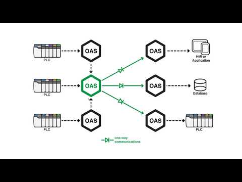
As outlined on the Networking Overview page, the Unidirectional Network Gateway can be used to pass data from one OAS engine to another in a way that ensures data can only flow from the source to the destination and never the other way around. Normally, when an OAS engine uses Basic Networking or Live Data Cloud, one OAS engine can both read and write remote tags on another OAS engine. This type of communication is often used with remote data logging and Data Route. Whilst it is possible to use permissions to prevent reading and witing tags, this level of isolation is not sufficient for some use cases. The Unidirectional Network Gateway aims to solve this problem using a lower level isolation approach.
The Unidirectional Network Gateway is in fact also known as UDP Broadcast and UDP Receive, because it makes use of UDP – User Datagram Protocol – to create unidirectional data streams. By using UDP instead of TCP, the data can be sent from the source engine to a destination engine UDP port, which ensures data can only flow from the source to the destination OAS engine and not the other way around.
In the source OAS engine, you will specify the destination IP or host and port number on the UDP Broadcast screen. One destination OAS engine on the other hand, you will specify a port on which to listen for tag changes. These two port numbers must match. The following diagram shows an example:
The feature is included for free in all OAS systems.
See the following video for more practical information.
The feature supports broadcasting data from any tag variable from a the local server or remote servers within a local network to unlimited number of receiving servers. Each receiving server can be setup to receive data from multiple broadcast servers providing many to many data transfer.
Use the following steps to setup servers to broadcast data and receiving services to update local and remote tag variables from the broadcasting nodes.
The receiving nodes need to have a fixed IP address, registered domain name, or network node name. The broadcasting nodes do not need to have a fixed IP address.
Step 1
Start Configure OAS application.
Step 2
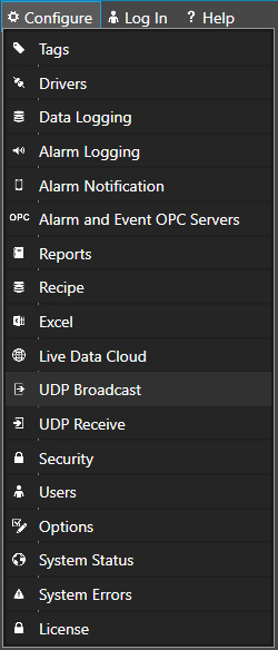
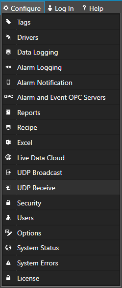
From the data source service select Configure-UDP Broadcast.
Step 3
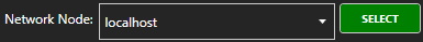
Select the Local OAS Service by selecting the Select button next to the Network Node drop down.
Step 4
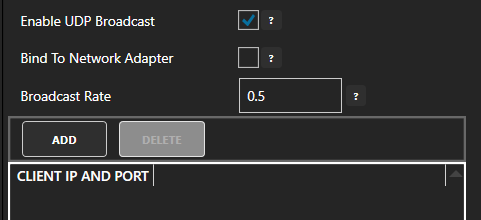
Click the Checkbox to Enable UDP Broadcast and enter the Broadcast Rate which is the rate all values from this service will be broadcast to the receiving clients.
Click on Apply Changes.
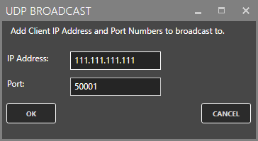
Click the Add Button and enter each receiving client IP Address and Port Number in the popup window and click OK.
Step 5
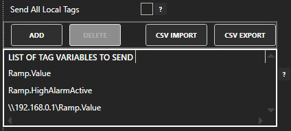
Choose to send all tag values from the local service on each broadcast or uncheck the property Send All Local Tags to define a list of tags from the local system, remote systems, and all variables.
By defining which tags to broadcast has the following benefits over Send All Local Tags.
Reduced network packet size on the broadcast if the number of tags sent is less then the number of local tags.
Can broadcast any Tag Variable, not just the Value.
Can broadcast tag values from other remote nodes within the DMZ.
Step 6
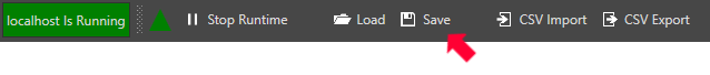
Select the Save button on the toolbar at the top.
Step 7
Save the file myUDPBroadcastServer.UDPBroadcast in the directory of your choice.
You can specify for this configuration to load automatically when the Service starts using Configure-Options to specify this default UDP Broadcast file.
Step 8
From the receiving service select Configure-UDP Receive.
Step 9
Select the Local OAS Service by selecting the Select button next to the Network Node drop down.
Step 10
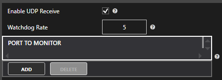
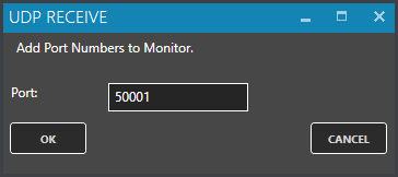
Click the CheckBox to Enable UDP Receive and enter the desired watchdog rate. The watchdog rate is the amount of time it will wait before setting the receiving tags quality to bad without receiving a broadcast.
Click on Apply Changes.
Click the Add Button to add a Port Number to listen on and select OK. You can enter multiple receiving port numbers.
Step 11
Select the Save button on the toolbar at the top.
Step 12
Save the file myUDPBroadcastClient.UDPReceive in the directory of your choice.
You can specify for this configuration to load automatically when the Service starts using Configure-Options to specify this default UDP Receive file.
Step 13
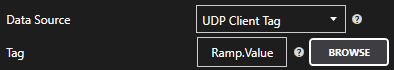
In the receiving node select Configure-Tags. Add Tag’s with the Data Source of UDPClientTag and enter the Tag name of the broadcasting node you want to receive the value from.
Keep in mind you may not be able to browse for the tag name from the broadcast node, so you may have to manually enter it or use Tag CSV Import or programmatic tag setup using .NET or REST API to setup multiple tags.
The Tag defined must match the broadcast tag name defined in Step 5.
Examples:
Ramp.Value
Ramp.HighAlarmActive
\\192.168.0.1\Ramp.Value
Save the Tag Configuration file and specify it to load automatically under Configure-Options-Default Files.
NOTE: The OASPCL assembly still ships with the OAS Platform installation for legacy support, but we have now made the OASData and OASConfig assemblies compatible with Xamarin projects. More information on how to use these assemblies can be found here:
An active subscription to the Apple Developer Program for iOS distribution via the App Store
An active Google Developer account for Android deployment via the Google Play Store
*Note: when developing for iOS with Visual Studio for Windows, you will need to have access to a Mac on your network that has XCode installed. Debugging and execution on the iOS Simulator actually runs on the connected Mac and not on the PC hosting Visual Studio.
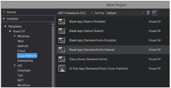
Create a new project in Visual Studio. If Xamarin is installed properly, this will be under Templates > Visual C# > Cross-Platform.
Select the project type of Blank App (Xamarin.Forms Shared). This will create a single shared application code base, and individual projects for each deployment target, including Android, iOS, Windows Universal Platform, Windows Phone and Windows.
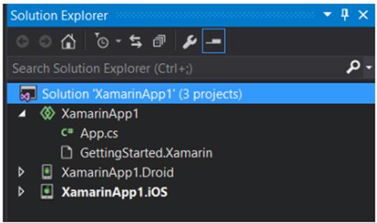
For this project we’ll only be using the Android and iOS projects, so once the solution is created, remove all other project targets so you’re left with just the shared app code and the projects for the the desired targets.
After clearing out the extra projects, your solution should look like this:
You need to add references to the following files in every individual deployment target project. So in this case, you need to add these references to both the iOS and Android projects.
OASData.dll
OASConfig.dll
These assemblies are the .NET Core Open Automation Software components for reading and writing Tag data and for configuring OAS Platform settings.
Step 4 – Code: add component instances
Update shared source code in the App.cs file. This will house all of the application code and will be shared by both iOS and Android projects to make it easier to maintain code for multiple devices.
First, add in a reference to the OASPCL namespace, along with application-level variables.
using System;
using System.Collections.Generic;
using System.Linq;
using System.Text;
using OASData;
using OASConfig;
using Xamarin.Forms;

namespace XamarinApp1
{
   public class App : Application
   {
       OASConfig opc = new OASConfig();
       OASData opcd = new OASData();
       string server = "10.211.55.3"; // your machine IP
       bool bPumpSet = false;
       bool bPumpVal = false;

       Label lblSine = new Label {
           Text = "Loading...",
           HorizontalTextAlignment = TextAlignment.Center
       };
       Label lblPump = new Label {
           Text = "Loading...",
           HorizontalTextAlignment = TextAlignment.Center
       };
       Button btnPump = new Button {
           Text = "Toggle Pump"
       };
The OASConfig component is used to configure OAS Server and tag settings, and is not used in this example, but the OASData component is.
This is used to monitor tags, fire events when values change on the server, and also to update values on the server. These are the local variables used:
Server – A string that holds a reference to the IP address of your OAS server where we will be reading and writing data. This may be the localhost of the machine with Visual Studio, but the compiled mobile apps may not be running locally, so localhost or 127.0.0.1 may not work. This needs to be the IP address on the network for your OAS server.
bPumpSet – A boolean flag that determines if we have gotten values from the server for the Pump.Value tag so we know when it’s safe to allow updates.
PumpVal – A boolean to hold the current value for the Pump.Value tag.
lblSine – A Xamarin Forms label to display the value of the Sine.Value tag
lblPump – A Xamarin Forms lable to display the value of the Pump.Value tag
btnPump – A Xamarin Forms button used to toggle the value of Pump.Value
Step 5 – Code: handle events
Now we’ll add some code to monitor server tags and handle updates when values change. The AddTag method adds a tag to the list of tags to monitor. You can also use the AddTags method to add more than one at a time.
The ValuesChangedAll event is fired every time the server values have changed for any tag being monitored. This event will be passed a list of tags, values, data qualities, and timestamps for each update. If values have not changed for some tags, they will not be included in the arrays passed to the event.
protected override void OnStart ()
{
   // set up tags
   opcd.AddTag(string.Format(@"\\{0}\Sine.Value", server));
   opcd.AddTag(string.Format(@"\\{0}\Pump.Value", server));

   // set up event handler
   opcd.ValuesChangedAll += Opcd_ValuesChangedAll;
}

private void Opcd_ValuesChangedAll(string[] Tags, object[] Values, bool[] Qualities, DateTime[] TimeStamps)
{
   // iterate thru received values and update display
   Device.BeginInvokeOnMainThread(() => {
       int idx = 0;
       foreach (string t in Tags)
       {
           if (t.Contains("Sine.Value") && Values[idx] != null)
           {
               lblSine.Text = Values[idx].ToString();
           }
           if (t.Contains("Pump.Value") && Values[idx] != null)
           {
               bPumpSet = true;
               bPumpVal = (bool)Values[idx];
               lblPump.Text = bPumpVal.ToString();
           }
           idx++;
       }
   });
}
In the event handler, we will iterate through the list of tags and update labels when their respective values have changed.
Note: We must execute UI updates within a Lambda (a C# anonymous function) tied to the Device.BeginInvokeOnMainThread. This hands over the execution to the main UI thread. If this is not done, crashes or unexpected results could occur.
Step 6 – Code: update screen
The last bit of code will be to handle the clicking of a button and triggering an update on the server when that happens. First we’ll update the App constructor to include the new labels and button in the layout. Then we add a Clicked handler to the button.
public App ()
{
   // The root page of your application
   MainPage = new ContentPage {
       Content = new StackLayout {
       VerticalOptions = LayoutOptions.Center,
           Children = {
               lblSine,
               lblPump,
               btnPump
           }
       }
   };
   btnPump.Clicked += BtnPump_Clicked;
}

private void BtnPump_Clicked(object sender, EventArgs e)
{
   // change pump value here
   if (bPumpSet)
   {
   Device.BeginInvokeOnMainThread(() => {
       opcd.SyncWriteTags(new string[] {
           string.Format(@"\\{0}\Pump.Value", server) },
           new object[] { !bPumpVal });
       });
   }
}
We use the SyncWriteTags method to send up a list of tag/value pairs. In this case we’re just sending up the Pump.Value tag and the inverse of the current value to effectively toggle it.
Step 7 – Building and testing for Android
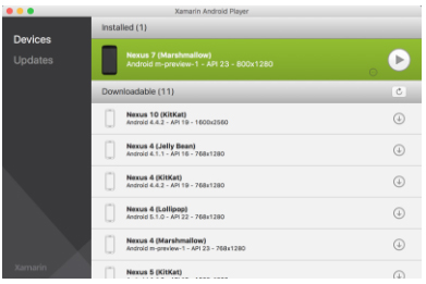
Start by running the Xamarin Android Player. If you do not have this installed, you can download it here. You’ll then need to download and install device images that the Player will use. For this example, we chose the Nexus 7 with Marshmallow build of the Android OS.
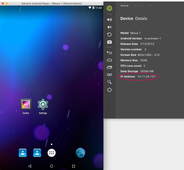
Once you’ve downloaded the device image you can start it up by hitting the Play button. This will run the device emulator. After the device has started, you can then click on the gear icon to get details. The important field is the IP address. We’ll use this to connect Visual Studio for debugging.
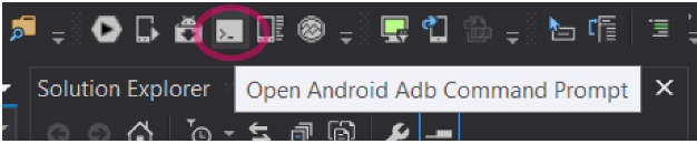
Now, you can go back to Visual Studio, select the Android Project, to be sure we’ll be debugging that one and not the iOS version. Select Debug to ensure we are in Debug and not Release mode. Then go to the set of icons in the toolbar and select Open Android Adb Command Prompt:
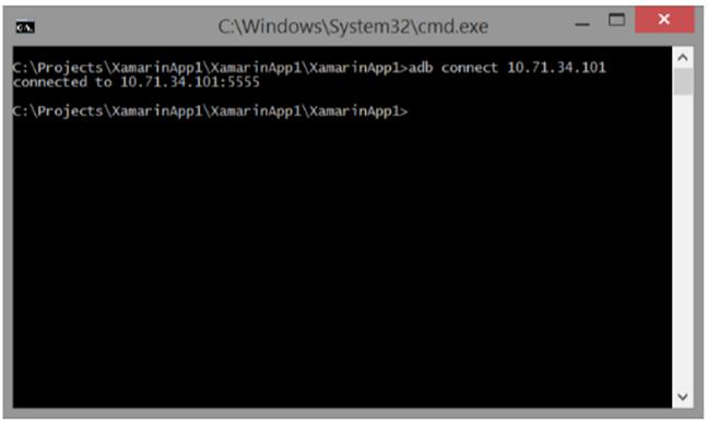
When the command prompt opens, enter the following command:
adb connect 10.71.34.101
Replace the IP above with the IP of your Android device.
You should see a successful connection. You’re now ready to debug the project.
In the Visual Studio toolbar, make sure your Android Device is selected as the target and then select Start Debugging. The project will build and then be deployed to the device.
Note: If you get an error related to missing “provisioning profiles”, this is common. To fix it, select the iOS project, then be sure to select the iPhoneSimulator as the target. Then return to the Android project and try again. Even though we were debugging the Android project, the iOS project will compile and throw errors.
Step 8 – Building and testing for iOS
As stated earlier, to build and test an iOS app, you must be connected to a Mac on your network. This Mac must have XCode installed along with the Xamarin Mac Agent. This allows Visual Studio to connect to the Mac and use its Simulator for debugging.
The simplest way to get the Xamarin Mac Agent on your test machine is to install Xamarin Studio for the Mac found at http://www.xamarin.com/download.
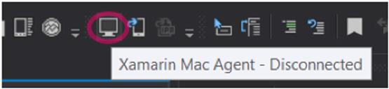
Once you have your Mac configured and accessible on the network, return to Visual Studio to connect by selecting Xamarin Mac Agent from the toolbar:
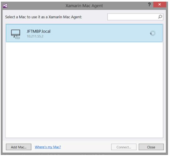
Locate your Mac in the list and click Connect. If it is not on the list, click Add Mac… to enter connection details manually.
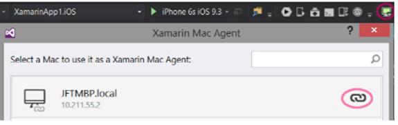
Once connected, the toolbar icon will change and the link icon will appear in the Xamarin Mac Agent dialog:
You can now select the iOS project and target the iPhoneSimulator, choosing the model you want to test. In this case we’ve chosen the iPhone 6s. The models and iOS versions available to you will depend on the version of XCode and Simulator installed on your Mac.
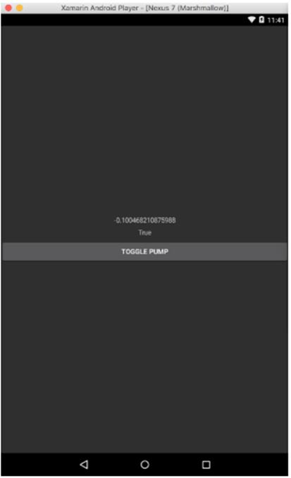
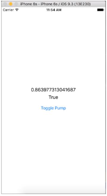
Now select Start Debugging and the app will compile, deploy to the simulator and start. Switch over to your Mac and you should see it running.
As you can see, the labels and button are similar to those on the Android version, but particular to the iOS app. This allows you to develop an app that is familiar to each target platform user while remaining on a single code base.
Resources
For more details on how to use the OPCSystemsComponent or the OPCSystemsData components, you can refer to the Programmatic Interface section of our online help. The PCL versions of these components have the same interface as the standard .NET components, so all code examples will function in the same way.
Tags can also be used without a data source with a static value to update from programmatically from a .NET application or REST API or from a user interface.
Calculation can be another source for tags with values from other local or remote tags.
The following section is how to manually add and define Tags using the Configure OAS application. Tags can also be added and modified using the CSV Import and Export selections using the Configure-Tags application to use Excel or other third party Comma Separated Variable editor.
To learn how to programmatically add or modify Tags from your own Visual Studio application refer to the following article on how to add and define multiple tags with one method:
Please view the Getting Started with Open Automation Software Video to familiarize yourself with installation, setting up Tags, selecting Data Sources and Destinations, and implementing Networking and Security.
Step 1 – Start Configure App
Start Configure OAS application from the program group Open Automation Software.
Select Configure-Tags.
NOTE: The Configure application can be used to connect to remote systems using the network node name or IP address of the remote node the OAS Service is running on. Simply enter the IP Address or network node name of the remote OAS Service you wish to connect to and click on the Select key.
When selecting a service if you receive a warning dialog that the service cannot be retrieved make sure the OAS Engine is started.
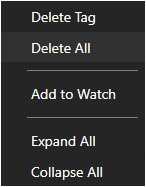
If you already have the default Demo Tags loaded you can right in the Tags root and select Delete All Tags.
Step 2 – Add Tags
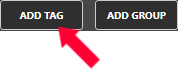
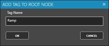
Click on the Add Tag button located at the top of the Tag browser.
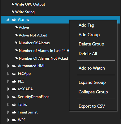
NOTE: You can also add organizational Groups as many levels deep as you prefer and add tags to groups. To do this first add a Group to the root level, then right click on the Group in the right window to add additional Groups or Tags.
Enter the Tag name Ramp in the Add Tag dialog box.
Repeat Steps 4 and 5 with Tag name Sine.
Repeat Steps 4 and 5 with Tag name Random.
Step 3 – Modify Tags
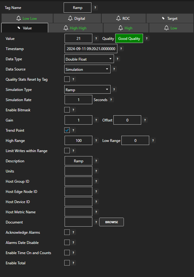
Select Tag Ramp in the right Tag window.
All Tag properties will appear in the lower window.
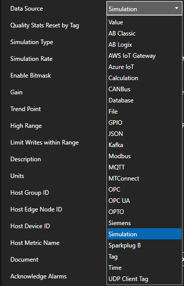
For the Value Parameter set the Data Source to Simulation.
If you plan to use trending on this point enable the Trend Point option.
Set the Description field to Ramp.
Select the High High Parameter and set the Value field to 80 and enable the High High alarm.
Select the High Parameter and set the Value field to 60 and enable the High alarm.
Select the Low Parameter and set the Value field to 40 and enable the Low alarm.
Select the Low Low Parameter and set the Value field to 20 and enable the Low Low alarm.
Select the Apply Changes button in the lower right corner.
Select Tag Random and the Value Parameter.
For the Value Parameter set the Data Source to Simulation.
Set the Simulation Type to Random
If you plan to use trending on this point enable the Trend Point option.
Select Tag Sine and the Value Parameter.
For the Value Parameter set the Data Source to Simulation.
Set the Simulation Type to Sine
If you plan to use trending on this point enable the Trend Point option.
Set High Range to 1 and Low Range to -1.
Step 4 – Save Configuration
Select the Save button on the toolbar at the top.
Enter a file name to be saved in C:\ProgramData\OpenAutomationSoftware\ConfigFiles directory on Windows or ConfigFiles subdirectory on Linux.
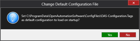
When prompted to set the file as the default configuration to load on startup select Yes.
The default file can be changed under Configure-Options-Default Files.
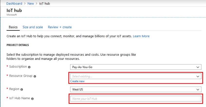
In the IoT Hub Name field, enter a name for your hub. If the Name is valid and available, a green check mark appears in the Name box.
Step 6
When you have finished entering your IoT hub configuration options, click Review + Create at the bottom of the page. On the next page, review your details and then click Create.
Step 7
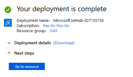
A page will appear that says: Your deployment is underway.
It can take a few minutes for Azure to create your IoT hub. Be patient.
When it is done you will see a page that says: Your deployment is complete. Click the Go to resource button.
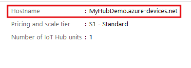
Step 8
The page you now see gives you an Overview of your new IoT Hub. On the top right side of the page, you will see the Hostname for your hub. Copy this somewhere because you will need it later on in the tutorial to set up your OAS driver.
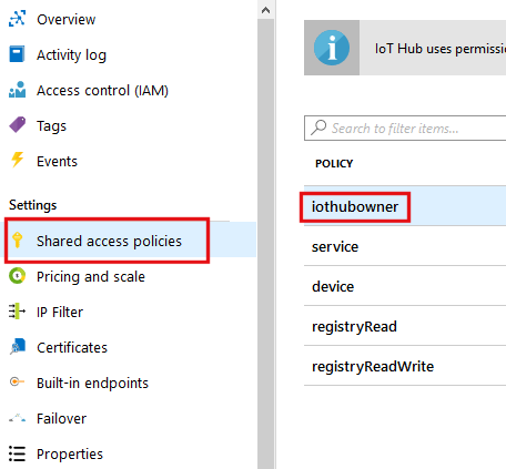
Step 9
Next click Shared access policies from the left menu. In the pane that appears to the right, click iothubowner.
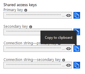
In the panel that appears to the right, select the Copy to clipboard icon next to Connection string – primary key. Save this as well, you will need it later.
You have now created your IoT hub and you have the hostname and connection string you need to complete the rest of this tutorial.
Create an IoT Driver
Step 1
Open Configure UDI.
Step 2
Select Configure >> Drivers from the top menu.
Step 3
Select your Network Node, either local or remote.
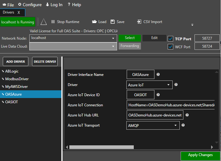
Step 4
Enter the Driver Interface Name you wish to use.
Step 5
Select Azure IoT from the Driver combo box.
Step 6
Enter the Azure IoT Device ID you want to use.
Step 7
Enter the Connection String from Step 9 of the previous section into the Azure IoT Connection field.
Step 8
Enter the hostname from Step 8 of the previous section into the Azure IoT Hub URL field.
Step 9
To enable data buffering when communication failure occurs check Enable Store and Forward. Values will be stored in the directory specified under Configure >> Options >> Store and Forward.
Step 10
Select the preferred Azure IoT Transport. Typically it is AMQP.
Optionally define a secondary failover IoT Hub URL if the primary server fails with the property Enable Failover.
If both the primary and secondary servers are offline the Return to Online settings determines the retry frequency.
View Driver Interface Failover for more information and and video demonstrating communications failover.
Step 11
Click Add Driver on the top left.
Publish Live Data to your Azure IoT Hub.
There are 2 ways to publish data from OAS to Azure IoT Hub. Both require Tags to be setup first for the data sources you want to transfer.
Option 1 – Publish Selected Tags to your Azure IoT Hub.
View the following video for a complete demonstration of how to publish data to Azure IoT Data Hub.
00:00 – Introduction
00:23 – Set up Tags in OAS
00:41 – Configure Azure IoT
01:53 – Publish Selected Tags
05:31 – Visual Studio Code
08:00 – Step by step instructions
08:12 – Bulk Publish to AWS IOT
09:21 – Step by step instructions / Publish Data to AWS IOT Gateway
09:33 – Bulk Publish to mqtt broker
10:29 – MQTT Explorer
11:20 – Step by step instructions/ Getting Started MQTT
11:34 – Save button of the OAS Configuration tool
Step 1
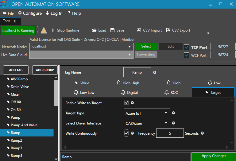
Enable Publish Selected Tags at the bottom of the Driver configuration.
Step 2
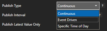
Select to publish data continuously at a specified interval, based on event, or at a specific time of day.
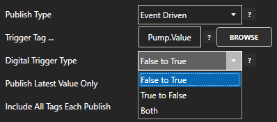
If Event Driven browse for a local or remote OAS tag that will trigger the publish. Select a Boolean tag that will change state from false to true, true to false, or both. Or choose an Integer tag that trigger a publish anytime the value changes other than 0.
Step 3
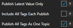
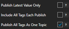
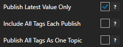
Enable Publish Latest Value Only to send only the latest value of each tag when published or disable to send all value changes since the last time a publish occurred.
Enabled Include All Tags Each Publish to send at least the latest value of each tag when published or disable to only send the tags that have changed since the last publish.
Enable Publish All Tags As One Topic to publish all tag values as one topic or disable to send each tag as its own topic.
See examples in Step 6 below for each selectable option.
Step 4
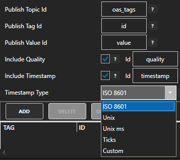
Specify the Publish Topic Id if choosing to Publish All Tags As One Topic.
Specify the Tag Id, Value Id, an optional Quality Id, and Timestamp Id for each tag value that is sent.
When including the Timestamp Id also specify the timestamp format, use Custom to specify your own date and time format.
Step 5
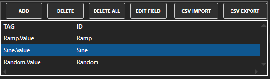
Specify local and remote OAS tag variables to include in each publish and specify the Id. Value is the current value from the data source or you can select any of the over 600 tag variables of each tag to publish.
Optionally use CSV Export and CSV Import buttons to set up additional tags to publish using Microsoft Excel.
Once you have unzipped it you can open it with Visual Studio or Expression Blend.
NOTE: If you want to visualize your data in a desktop or mobile browser with zero programming, you may be interested in the OAS Open UIEngine .
The UIEngine is a robust no-code web application and HMI builder for developing rich user interfaces in a browser-based development environment.
See the UIEngine Documentation to learn more.
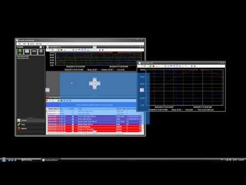
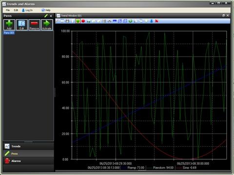
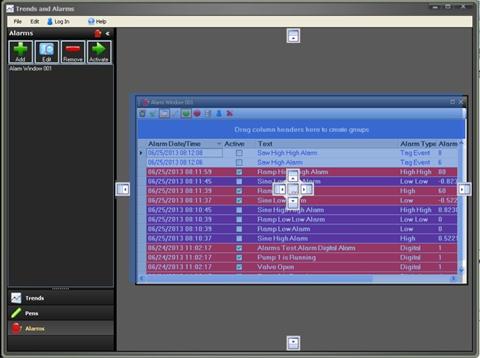
You can view Trends and Alarms Dashboard video to review the steps of using this application.
0:00 – Introduction
0:06 – what’s Trend and Alarm Historian Application
0:30 – Pens Groups
0:41 – Trend Windows
0:51 – Include Pens to Trend Window
1:13 – Pens Properties
1:27 – Trend Type
1:34 – Time Frame
2:04 – Stack Chart Mode
2:28 – View
2:52 – Trend Window – Workspace
3:09 – Pens Group
3:16 – Add Pen Group
4:08 – Duplicate Pen Group
4:31 – How to use the Pens
4:39 – Create a new Window without pens
5:34 – Alarms Panel
5:41 – Activate Alarms Windows
6:24 – Customize Alarm Window
6:55 – Modifying Attributes
8:21 – Docking Panels
8:33 – More Questions – Contact Us
9:05 – Training Page – more videos
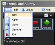
Menu
File-New: Clears all trend, pen groups, and alarm windows and starts with a blank configuration.
File-Open: Opens an existing configuration previously saved.
File-Save: Saves the current configuration with the existing file name. This will save the list of Trend, Pen Groups, and Alarm Windows and the current list of Windows in the View Window.
File-Save As: Saves the current configuration and with a desired file name.
File-Exit: Exit the application.
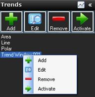
Trend Navigator Bar
The Trend Navigator Bar is used to add, modify, and deleteTrend Windows that can be selected to be added to the current view configuration.
To view the list of Trends select the Trends button at the bottom of the Navigator Bar.
Add Trend:
Select the Add button to add a Trend Window to the configuration. This will display the Trend Window setup form.
You can define a list of pens to be used with the trend on startup or use the Pen Groups feature and leave the list of Pens blank.
Networking:
If you will be deploying the Trends and Alarms Dashboard configuration to remote PCs or using the application on a different PC than where the OAS Engine resides implement either Basic Networking syntax or Live Data Cloud Networking syntax by entering the IP Address or Network Node in the Network Node field and click Select or optionally select the Live Data Cloud node where the tags are hosted.
Enter the desired Trend Window Name that will identify the Trend Window in the configuration. You must use a unique name that does not already exist.
Select OK to accept the changes or Cancel to abort the recent changes to the window.
Make sure to select File-Save if you add a Trend Window.
Edit Trend:
Select an existing Trend Window from the Trend List and then Modify button to modify the Trend Window. This will display the Trend Window setup form.
Remove Trend:
Select one or more existing Trend Windows from the Trend List and then the Remove button to remove the Trend Windows from the configuration.
Make sure to select File-Save if you remove a Trend Window.
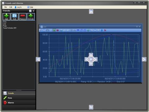
Activate Trend Window:
Select a Trend Window from the Trend List and then the Activate Trend Window button or simply drag the Trend Window name into the main application to add the Trend Window to the view screen. You can add the same Trend Window more than once if you desire as you can make on-line modifications.
Once the Trend Window is activated the window can be left as free floating to any size or location or it can be docked within the main docking area.
Select File-Save after the Trend Window is docked or placed into the location you would like it to be.
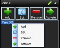
Pens Navigator Bar
The Pens Navigator Bar is used to add, modify, and deletePen Groups that can define a list of pens to add to an existing Trend Window that is activated.
To view the list of Pen Groups select the Pens button at the bottom of the Navigator Bar or select Edit-Pens.
Add Pens:
Select the Add button to add a Pen Group to the configuration. This will display the Pens setup form.
Enter the desired Pen Group Name that will identify the list of Pens in the configuration. You must use a unique name that does not already exist.
Select OK to accept the changes or Cancel to abort the recent changes to the Pen Group.
Make sure to select File-Save if you add a Pen Group.
Edit Pens:
Select an existing Pen Group from the Pens List and then Edit button to modify the Pen Group. This will display the Pens setup form.
You can use the Edit function to also clone an existing Pen Group to a new Pen Group simply by specifying a Pen Group name in the pens properties dialog.
Select OK to accept the changes or Cancel to abort the recent changes to the Pen Group.
Make sure to select File-Save if you modify the Pen Group.
Remove Pens:
Select an existing Group from the Pens List and then the Remove button to remove the Pen Group from the configuration.
Make sure to select File-Save if you delete a Pen Group.
Activate Pens:
Select an existing Pen Group from the Pens List and then drag the pen name to one of the trend windows that are currently activated.
Select File-Save after the Pens have been activated to a trend window.
Alarm Navigator Bar
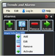
The Alarm Navigator Bar is used to add, modify, and delete Alarm Windows that can be selected to be added to the current view configuration.
To view the list of Alarms select the Alarms button at the bottom of the Navigator Bar or select Edit-Alarms.
Add Alarm:
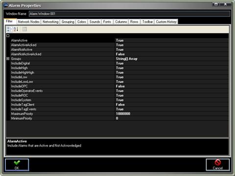
Select the Add button to add an Alarm Window to the configuration. This will display the Alarm Window setup form.
Networking:
If you will be deploying the Trends and Alarms Dashboard configuration to remote PCs or using the application on a different PC than where the OAS Engine resides use the Networking tag to select all remote nodes where the alarms will be hosted from.
Enter the desired Alarm Window Name that will identify the Alarm Window in the configuration. You must use a unique name that does not already exist.
Select OK to accept the changes or Cancel to abort the recent changes to the window.
Make sure to select File-Save if you add an Alarm Window.
Edit Alarm:
Select an existing Alarm Window from the Alarm List and then Edit button to modify the Alarm Window. This will display the Alarm Window setup form.
You can use the Edit function to also clone an existing alarm window to a new alarm window simply by specifying a new window name in the alarm properties dialog.
Select OK to accept the changes or Cancel to abort the recent changes to the window.
Make sure to select File-Save if you modify the Alarm Window.
Remove Alarm:
Select an existing Alarm Window from the Alarm List and then the Remove button to remove the Alarm Window from the configuration.
Make sure to select File-Save if you delete an Alarm Window.
Activate Alarm Window:
Select an existing Alarm Window from the Alarm List and then the Activate button to add the Alarm Window to the view screen. You can add the same Alarm Window more than once if you desire as you can make on-line modifications.
Once the Trend Window is activated the window can be left as free floating to any size or location or it can be docked within the main docking area.
Select File-Save after the Alarm Window is docked or placed into the location you would like it to be.
The Example application installed with Open Automation Software is a Smart Client compatible application demonstrating remote connectivity to any Open Automation Software Service. The application includes OPC Controls.NET, OAS Trend .NET, OAS Alarm .NET, and the OAS Configuration component.
When building your own Smart Client application make sure to include either the Network Node name or IP Address of the OAS Services you wish to connect to. This would include the OPC Controls Tag properties, the OPC Trend pen Tag names, the OPC Alarm window network nodes, and any routines using the Open Automation Software programmatic interface.
Open Automation Software uses TCP port number 58724, so be sure to add your applications you deploy to any firewalls on your system with this TCP port number as an exception. The TCP port number is adjustable in both the service and as the WCFPortNumber property in each .NET dll.
To deploy applications with Visual Studio 2005 with the .NET Framework 2.0 is extremely simple.
Step 1
Make sure IIS is installed and running on the system you wish to deploy to.
Step 2
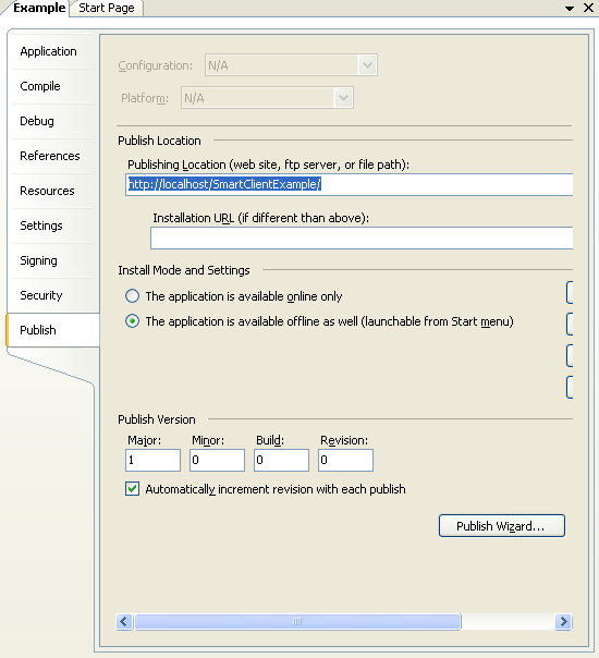
In Visual Studio 2005 select the Properties of the project you wish to deploy.
Next select the Publish tab to view the Click Once deployment section.
Step 3
Set the Publish Location to the local or remote system that is running IIS.
Step 4
Set the initial Publish Version and either leave the automatic increment or disable the feature and set it manually each time you want to make an update to the application.
Step 5
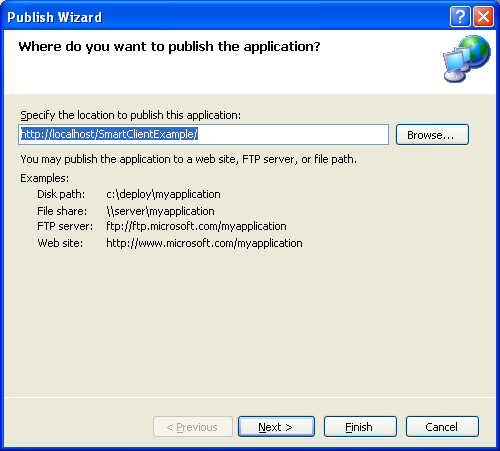
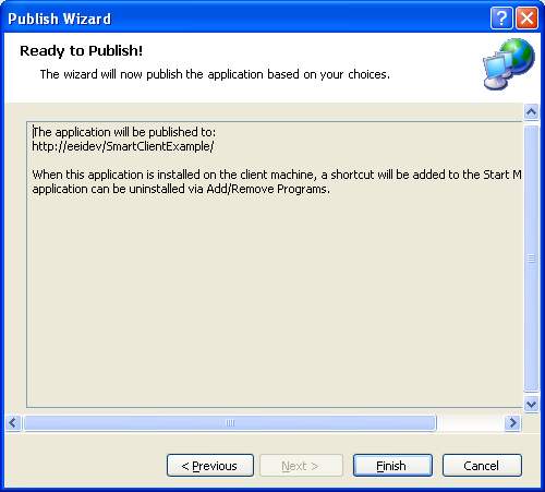
Select the Publish Wizard button to begin the steps of deploying the application.
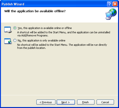
Step 6
Determine if the application will be installed remotely to run on each system even if the server is not reachable or if the application will only be available with the server is online.
Step 7
Confirm that the deployment virtual directory is correct and select Finish.
Step 8
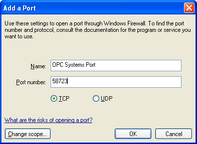
Open port 58724 on all systems that will be communicating together that have a firewall enabled.
On each OAS Service system that you wish to connect to and each remote system you will be running the application from add TCP port number 58724 if a firewall is enabled. This port number is adjustable in the service and in all .NET dlls.
For Windows XP SP2 Select Control Panel-Windows Firewall.
Select the Add Port button.
Enter a Name and the Port Number 58724.
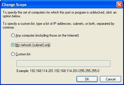
Use the Change scope button to limit the IP range to the systems that will be communicating together.
Step 9
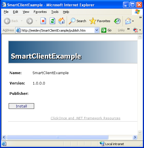
From any remote client system simply open url of the deployment server publish page using a web browser and select the Install button.
With Smart Client deployment you can now easily deploy updates to one location and make updates just to the one deployment server and all remote users automatically receive the updates on the next time they run the system.
When the application is installed for offline/online deployment each time it runs it connects to the deployment server to see if there is a newer version available. The user is prompted to install the update or ignore and continue to run the application.
Networking functionality is a core feature of Open Automation Software and is also known as the Distributed Network Architecture (DNA) feature. As outlined in the Networking Overview, there are three main communication types that OAS provides for transferring tag data between OAS Engines and clients depending on what networking architecture is required:
These methods can be used in isolation or together to achieve different types of networking architectures and allow you to move you data from your data sources to your data destinations.
Within the context of OAS Networking discussed here, a client could be defined as another OAS Engine or one of the OAS .NET connectors or .NET HMI or Web HMI components used for reading and writing tag data. Whilst features such as the REST API, MQTT and Cloud based connectors are also used to transfer tag data, these are not considered core features of OAS but rather considered separate drivers with independent configuration options.
When is Networking used?
The Networking functionality of OAS is used whenever you move data between two or more OAS Engines or between an OAS Engine and one or more OAS clients. More specifically, when we are talking about data, we are actually talking about Tag data. A Tag is the fundamental representation of a unit of data in OAS and consists of a value, a timestamp and a quality state. The tags you define and organize in OAS represent your data model – be it a business process, a monitoring processes or some other logical representation of a physical state.
Using the configurable features of OAS, you can move tag data between engines and between engines and clients without having to do the heavy lifting of implementing any communications protocols yourself. Your own custom solutions and applications can leverage existing OAS libraries to read and write data – all you need to know is the tag path, name and parameter name you wish to read or write. The power of OAS Networking becomes more apparent with an understanding of Remote Tag Access.
When a tag is referenced locally to a particular OAS Engine (for example, by setting a tag’s data source to Tag and pointing to another tag) or from a client connected to a particular instance, it can be simply referenced by the path, name and parameter, as mentioned previously. This looks something like this:
MyTag.Value
Let’s now look at how you might reference a tag on a remote OAS Engine. In other words, an OAS Engine or client referencing a tag that is not on the same OAS Engine or the OAS Engine that the client is connected to. This is where the Basic Networking communication comes in. When you want to reference a tag on a different OAS Engine it is as easy as adding the remote node’s IP address, host name or domain name.
\\Instance1\MyTag.Value
OAS will handle all of the engine to engine data transfer automatically and you do not need to do anything differently in your clients. In the diagram above, you can see that the client is connected to Instance2, but the tag reference is a remote tag reference. Instance2 will automatically route the request to Instance1 and retrieve the data. Depending on if you are using a .NET or a Web client (see next section) the remote tag access will be configured slightly differently.
The second remote tag access method is the Live Data Cloud method. This is where tag data is routed through an intermediate OAS Engine and is designed to allow separation of networks. In this type of communication, tags are referenced using the alias name of the Live Data Cloud host node. For example:
In this case the domain www.opcsystems.com represents the Live Data Cloud host node and Instance1 is the alias for one of your internal OAS Engine instances. The RemoteSCADAHosting prefix let’s OAS know that this special format is being used. The remainder of the tag path is the same as a standard tag reference.
These components will natively communicate with an OAS Engine using the core TCP networking functionality provided by OAS as explained in the Networking Overview.
The web clients on the other hand use HTTP based protocols to communicate with the OAS Engine. These components include:
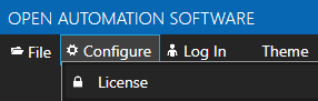
Networking functionality is enabled with the DNA feature enabled in your license. You can check your license in the OAS Configuration tool by going to the Configure > License screen and checking that you can see the phrase Networking is Enabled.
There are some architectures that do not require networking, such as hosting services on one server
The Live Data Cloud hosting server does not need a license as its only purpose is to route traffic between data source servers and clients. Your OAS Engine at the data source will typically be licensed for the features and drivers that you require.
Configuration
For OAS Engine configuration changes you have the option to use the OAS Configuration tool or to use the .NET OAS Configuration SDK or the Server Configuration REST API. From this point on this guide will only mention the OAS Configuration tool in order to minimize duplication.
Limits
➡️ Each OAS Engine can support up to 10,000 simultaneous client connections.
➡️ Each client application can support connections with up to 10,000 independent OAS Engines.
➡️ The resources of your hosting server or environment as well as the networking bandwidth and connection quality may play a role in the overall performance of the system. It is important to monitor the CPU, memory, storage and network throughput of your environment to ensure OAS is performing as expected.
Polling Rate
Clients will request tag data from an OAS Engine at a regular interval. The first poll will send all requested tag data and any subsequent poll will only send data changes.
The default polling rate for clients is 30 milliseconds. This can be configured using the OAS Configuration tool on the Networking tab of the Configure > Options screen.
Recommended polling intervals for larger number of client connections:
> 100 client connections — 100ms
> 1,000 client connections — 1,000ms
⚠️ The OAS Engine will need to be restarted for the change to take effect.
Listening Ports
OAS uses a number of standard ports for communication between OAS Engines and clients depending on the technology that is used.
OAS Engine and .NET client OAS components
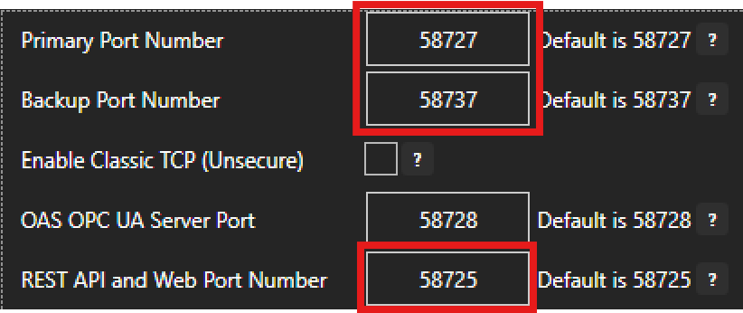
For OAS Engine to OAS Engine and for OAS Engine to non-web client OAS component communications two ports are exposed on the OAS Engine. These are called the primary and backup ports. These ports provide a bidirectional, compressed and encrypted data stream.
Port 58727 – Primary Port Number
Port 58737 – Backup Port Number
The backup port is used to listen for incoming client connections should there be a problem with the primary port. The OAS Engine will automatically attempt to use the backup port if the primary port is not available. The following diagram illustrates OAS Engine to OAS Engine communications.
The following diagram illustrates OAS Engine to non-web clients where the OAS Dotnet libraries are used for OAS Engine communications. This allows OAS components and HMIs to use the same benefits of compression and encryption. Note that all of the non-web clients will use the primary port, except the OAS Configuration Tool which will use the backup port if the primary port is not available.
Web clients
Web based clients and REST API clients use a different port to the primary and backup port exposed by the OAS Engine. This is because the web-based components do not use the same TCP stream based data transfer, but instead require a HTTP style communication API.
Port 58725 – Web and REST API Port Number
The Web API port is used for web-based clients such as the Web HMI JavaScript based features and controls. It is also used by the REST API and UIEngine.
Legacy Ports
There are two legacy port numbers used for communicating with old versions of OAS using the WCF or the .NET Remoting frameworks.
Port 58724 – Legacy WCF Port Number for OAS version 11 or older
Port 58723 – Legacy .NET Remoting Port Number for OAS version 4 or older
These port numbers are not configurable and are not available on Linux. To enable communication with a legacy OAS version using .NET Remoting, you can enable this feature by ticking the Enable Classic TCP (Unsecure) checkbox.
Port Configuration
The primary, backup and web ports listed in previous sections are configurable using the OAS Configuration tool on the Networking tab of the Configure > Options screen. Note that if you make changes to these ports there may be other applications that need to be updated. For example, the OAS Configuration tool and the OAS Service manager application will need to use the updated primary port to function correctly. Similarly, any OAS Engines or clients will need to be updated – for more details see the Change Network Port Numbers page.
Remote Services Ports
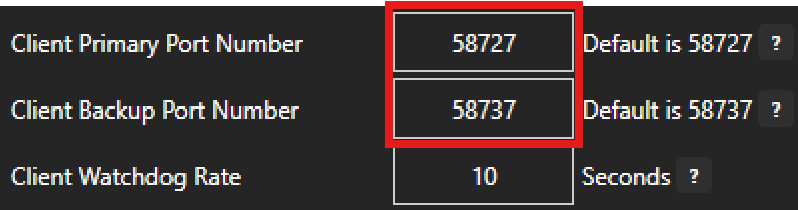
An OAS Engine (local engine) can communicate with a remote OAS Engine (remote engine) using the default port configurations as listed in the previous section. However, if you choose to change the listening ports on the remote engine and the local engine needs to communicate with the remote engine, then you will need to configure the Client Ports on the local engine to match the ports used by the remote engine.
You can configure the client port settings in the OAS Configuration tool on the Remote Services tab of the Configure > Options screen.
⚠️ Note that this setting will apply to all client communication initiated by the local engine. In other words, all remote engines that the local engine needs to connect to must have the same primary port numbers and the same backup port numbers. You cannot have a local engine that connects to two different primary port numbers or two different backup port numbers.
The Client Watchdog Rate parameter allows you to set a communication retry timeout on the local engine. If no communication is detected for the given number of seconds, the connection will be reset and a new reconnection attempt will be made.
Security
Access to reading and writing tag values is managed using OAS Security features. This includes creating user accounts with specific permissions that OAS Engines and clients will use to authenticate as well as mechanisms to manage permissions for reading and writing at the tag level.
View the video demonstrating the OPC Client .NET feature for OPC DA.
Step 1 – Check OPC Client License
After installing Open Automation Software verify you have a license of OPC Client on all OAS Engines that you want to interface with.
Start Configure OAS application from the program group Open Automation Software.
Use the Configure OAS application and go to Configure-License.
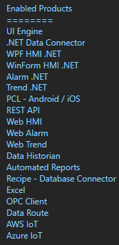
Check all OAS Engines that the OPC Client product appears in the Enabled Products list.
Step 2 – Installation and Setup
From each system with a Classic OPC DA Client, install either the full installation of Open Automation Software or the Custom installation with OPC Client Connector – OPCClient.NET. The Classic OPC DA OPC Server OPCSystems.NET requires the .NET Framework 3.5 to be installed in the operating system before installation.
NOTE: When networking third-party OPC Clients to remote OAS Services, always install the OPCSystems.NET OPC Server on the same computers as the OPC Client. You will not need a license on the OPC Client PCs, just where the data source is located with the OAS Engines.
Security Setup
In order to browse and access OAS tags from OAS Engines that have security enabled modify the file DANSrv.exe.config in the installation directory of OAS, typically C:\Program Files\Open Automation Software\OAS\.
Set both the UserName and Password within the file that would provide access to browse tags, read tags, and write tags.
To browse all 800+ variables of each tag set ValueOnlyBrowsing to False in the DANSrv.exe.config file.
Leave this settings as True to browse only the Value of each tag. (Recommended)
<add key=”ValueOnlyBrowsing” value=”True”/>
Network Setup
If the OPC Client is on a different computer than the OAS Service you are connecting to modify the file NetworkNodes.txt in C:\Program Files\Open Automation Software\OAS\ and add each IP Address, Network Node Name, or registered Domain Name you want to connect to the NetworkNodes.txt file.
Step 3 – Connect OPC Client
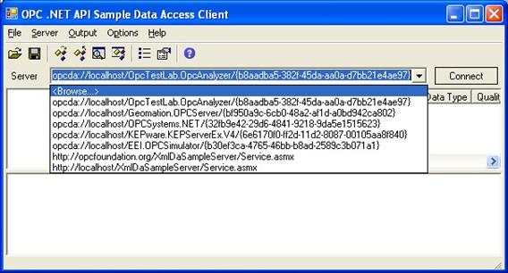
OAS is now ready to interface with a third-party OPC Client. In this example we will use the OPC Foundation Sample found under the program group Open Automation Software -Tools.
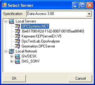
From the Server pull down list select Browse.
Select the local OPC Server OPCSystems.NET.
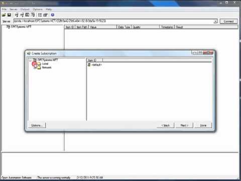
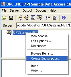
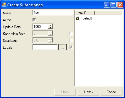
Create a group subscription by right clicking on the OPCSystems.NET OPC Server.
Enter a Name for the subscription and select Next.
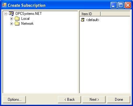
Step 4 – Browse OAS Tags
Browse either the Local service or a remote service under the Network branch.
Remote OPC Items use the following syntax for the remote OPC Item.
Network.<IP Address, domain name, or network node name>.Tag.Value.
Example: Network.192.168.0.1.Tag.Value.
NOTE: To browse remote OAS Engines modify the file NetworkNodes.txt as described in Step 1.
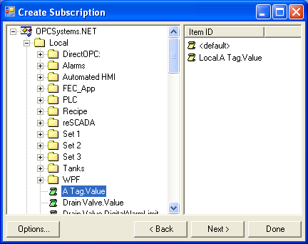
Browse for your OPC Item to add and double click on it.
Here you will see both Open Automation Software tags in the service you are browsing. DCOM is not used in remote connections. Networking is over TCP port 58727 and this port number is adjustable in the OAS Engine under Configure-Options-Networking and set in the DANSrv.exe.config file for each OPCSystems.NET OPC Server deployment.
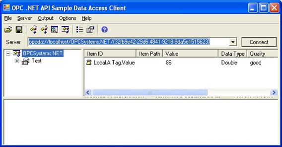
Select Next and then Done and the value of the remote item will appear.
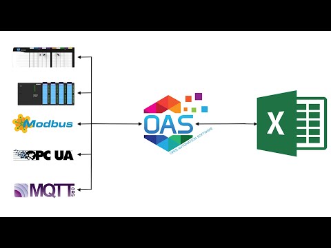
Follow the steps below for a simple setup for read and write functions in Microsoft Excel or view the following video.
00:00 – Introduction
00:08 – Setting OAS Connector
00:15 – Excel Configuration
02:14 – OAS Excel Tag Browser configuration
02:57 – Excel Formulas
03:50 – Excel ThrottleInterval
04:57 – Tag Browser
05:12 – How to write to a tag from Excel
06:19 – Tags Configuration
06:46 – Security Enable
07:30 – Deploy Excel
07:57 – Further Questions
These steps can be followed after downloading and installing OAS from the Support-Downloads page.
Step 1
Add the OASExcel Add-In to the operating systems Excel Add-Ins. You will only need to do this once on the operating system where the Excel Workbooks will be used.
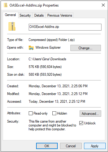
Right click on the zip file that you have downloaded. Check the Unblock checkbox for security as shown below. Click Apply.
Unzip and place the files in any directory you choose except for the OAS installation directory.
Start Microsoft Excel. and open an existing Workbook or new Workbook.
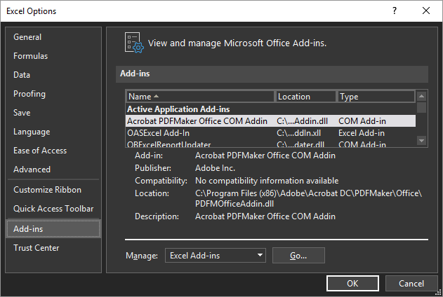
Select File-Options to open the Excel Options window.
Select Add-ins in the lower left and then the Go… button to the right of Manage Excel Add-ins.
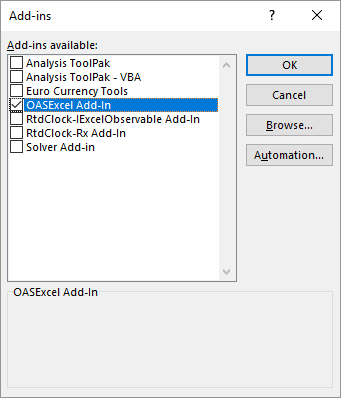
Select the Browse button and browse to the directory where you have placed the files to select OASExcel-AddIn.xll for 32 bit version of Excel or OASExcel-AddIn64.xll for 64 bit version of Excel and click OK.
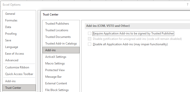
You may need to: change some setting in your Trust Center configuration if you are having issues.
Choose Options from the File menu. Choose Trust Center from the left menu, then click the Trust Center Settings button. Uncheck the top box for Require Application Add-ins to be signed by the Trusted Publisher.
Choose Trusted Locations from the left menu of the popup. Click the Add New Location button. Enter C:\Program Files\Open Automation Software\OAS\ and also check the box for Subfolders of this location are also trusted. Click Ok three times to exit popup.
Note: If you are uncertain which version of Excel you are running select File-Account and select the button labeled About Excel and you see either 32-bit or 64-bit at the top. Also if the OASExcel formulas do not appear in the next steps you most likely need to select the alternative xll file.
You are now ready to use the OASExcel formulas to read and write tag values to any local or remote OAS Engine with a license of OAS Excel.
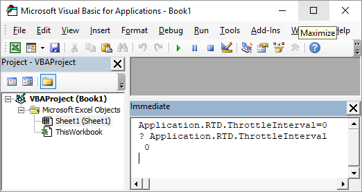
The Excel ThrottleInterval by default runs at 2 seconds in Excel. We recommend to change this default ThrottleInterval.
In Excel, go to the Visual Basic Editor by pressing ALT + F11.
On the Immediate Window at the bottom of the display, type this code: Application.RTD.ThrottleInterval=0
(Note: If the Immediate Window is not open, press CTRL + G to display the window.)
Make sure your cursor is on the line that you just typed and then press ENTER.
To verify that it is set correctly, type this line of code on the Immediate Window: ? Application.RTD.ThrottleInterval
Make sure your cursor is at the end of this line and then press ENTER. The window should display 0; then you know that your throttle interval is set correctly.
With the ThrottleInterval now set to 0 you will be able to achieve 30 millisecond updates from the OAS Engine. You will only need to perform this once on the operating system.
Step 2
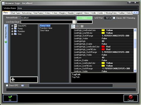
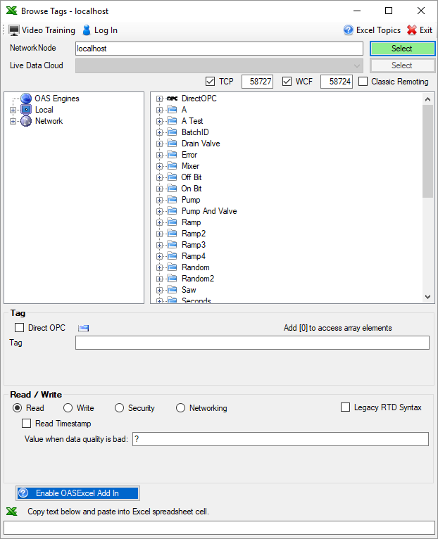
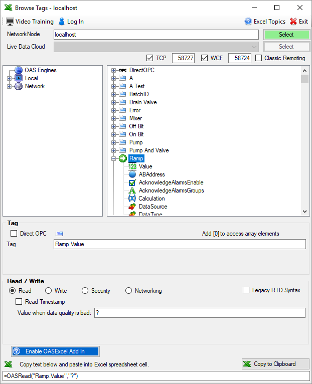
Use the OAS Excel Tag browse application to define read formulas to local and remote OAS Tags.
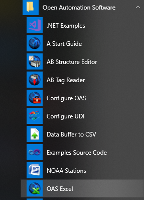
Start the OAS Exceltag browse application from the program group Open Automation Software.
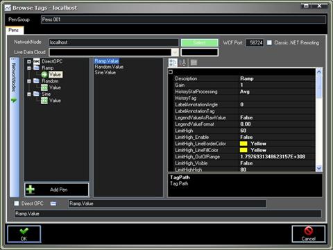
Select your Network Node in the Browse Tags window. Then use the Tags Tree to select desired Tag and Variable.
If the Workbook will be deployed to a remote computer or the OAS Engine resides on another computer enter the IP Address, registered domain name, or network node name of the remote OAS Engine where the tag resides to read or write to and click on Select. If self hosting OAS using Live Data Cloud networking select the Live Data Cloud node as well.
Value is the most commonly used Variable. See Tag Variables for a complete list of all variables possible.
If on the same computer leave Network Node as localhost and click on Select.
A list of tags from the remote service will appear.
Select a tag you want to read or write to from the tag list. In this example we will use OASRead function to read a tag Value.
Notice that the formula =OASRead(“Ramp.Value”,”?”) appears at the bottom of the window.
Copy this formula and paste into a Cell in Excel to read a value continuously from the local or remote OAS Engine.
The value will appear if the local or remote tag has good quality.
Use Ramp2 tag as a simulated value that changes every 100 milliseconds or any other tag you like that is changing faster than 1 second to check the ThrottleInterval.
=OASRead(“Ramp2.Value”,”?”)
Step 3
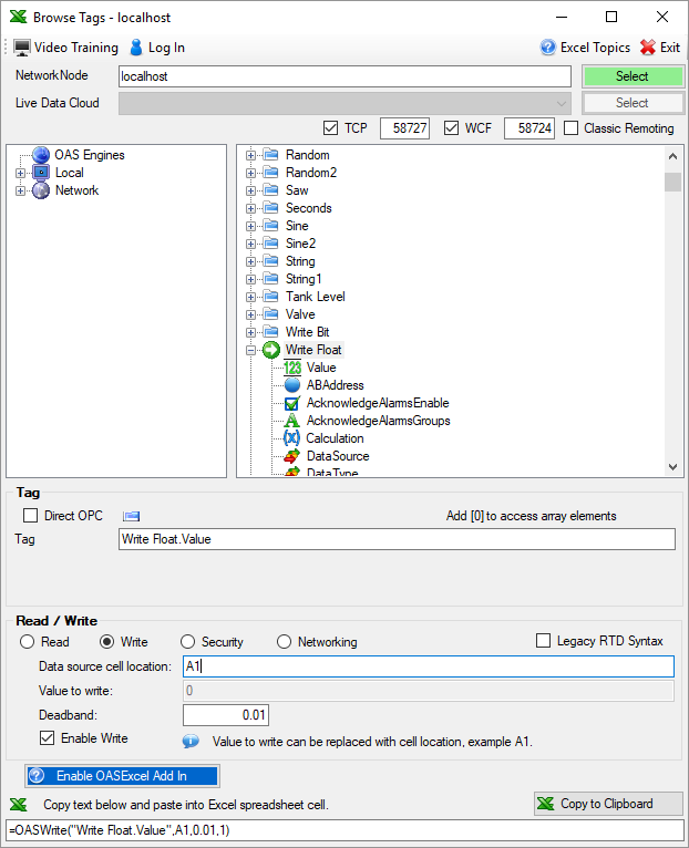
Optionally write to OAS Tags from Excel.
If you want to write to an OAS Tag go back to the OAS Excel Tag browse application and select the local or remote tag you want to write to and select the Write radio button. Enter either a fixed value in the Value to write field or enter a Cell location in the Data source cell location field. In this example we will write the value from cell A1 to the tag Write Float.Value.
Note: You can specify a deadband value that will disable the write if the value read back is within the range specified. This is useful when writing to single or double float values within a controller. You can also use the last parameter of the OASWrite formula to enable or disable the write entirely. This is useful to have all of the values preset in the workbook before writing the values to a controller, OPC Server, or other data source.
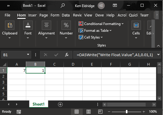
Copy the formula and paste into a Cell in Excel. In this example it will be place in Cell B2.
The OASWrite function automatically reads the OAS Tag value to determine if there is success in writing the value with full confirmation coming back from the Data Source of the Tag.
Following are the return values from the OASWrite function.
0 – Disabled
1 – Equal
2 – Value is being written
3 – Bad quality
4 – Cannot type cast value
5 – Unknown value to type cast
If the source value matches the value to be written a return value will be 1.
Step 4
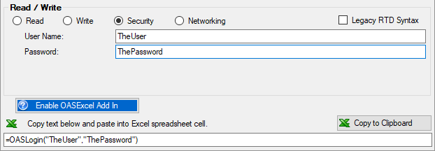
Implement security login
If the service you are connected to has Security enabled for reading or writing to tags you can specify the Security option in the OAS Excel tag browser and specify the User Name and Password for the Log In option.
=OASLogin(“TheUser”,”ThePassword”)
The User Name and Password can come from other cells that can be made hidden in the Excel Workbook if you like. In the following example the username and password would come from cells B10 and B11.
=OASLogin(B10,B11)
Step 5
Save the Excel Workbook. Open anytime in the future and the read and write functions will perform.
Step 6
If you plan to run the Workbook on a different PC than the OAS Service include the Network Node Name, IP Address, or registered Internet domain name in the tag path.
Tag:
\\www.opcsystems.com\Ramp.Value
Formula:
=OASRead(“\\www.opcsystems.com\Ramp.Value”,”?”)
To run the Workbook remotely you will need to repeat the steps to copy the files from the OAS Excel Add-In download Step 1 above to register the OASExcel-AddIn on that PC.
You only need a license of OAS Excel Connector on the data source PC where the OAS Service is running so you can run the Excel Workbooks remotely with an OAS Network License.