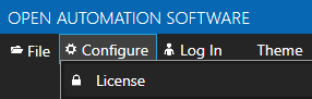
You can view what version you are currently running using the Configure application and select Help-Versions. On that dialog there is a button to take to the following to check current versions.
What is the price of the software?
View OAS Pricing for some basic examples.
Visit Request a Quote to request a product quotation.
Is there anything special that needs to be installed to run on Windows Embedded operating system?
Yes, the Microsoft Visual C++ libraries need to be installed. Download from the following.
http://www.microsoft.com/en-us/download/details.aspx?id=5582
Can I install Open Automation Software in silent mode?
Yes, run the following Setup.exe /s /v”/qn”.
Should I develop a WPF, WinForm, or HTML5 client application?
All support communications over the Internet, so networking is not a deciding factor.
Windows HMI is a good choice if:
- The customer is not experienced in creating WPF applications but has strong knowledge in building Windows Forms applications and the application is not graphics intensive.
- The application is for mainly displaying values.
- The customer wants to use Open Automation Software Controls in an existing Windows Forms Application.
- The customer wants to write a service to read and write data to Open Automation Software.
- The customer application will be running on Windows 2000 Professional.
WPF HMI is a good choice if:
- The customer has no preference and he want to use graphics.
- The customer would like Lamps, Switches, Shapes, Gauges, Pie Charts, Bar Charts, PID Controls or story boards built into the control library.
- The customer wants to be using the latest technology.
- The customer’s application is graphic centered as opposed to mainly a data display.
- The customer wants to automatically scale his application to the monitor size.
- The customer wants the ability to Scale, Rotate or Skew object in the application.
Web HMI is a good choice if:
- If you plan to run the application on a smart phone or non widows operating system.
I have a problem uninstalling Open Automation Software due to a missing MSI.
Try running the fix https://support.microsoft.com/kb/290301?wa=wsignin1.0
I am prompted to install the .NET Framework 3.5 during installation?
The .NET Framework 3.5 needs to be enabled.
a) Press “Windows Logo” + “R” keys on the keyboard.
b) Type “appwiz.cpl” in the “Run” command box and press “ENTER”.
c) In the “Programs and Features” window, click on the link “Turn Windows features on or off”.
d) Check if the “.NET Framework 3.5 (includes .NET 2.0 and 3.0)” option is available in it.
e) If yes, then enable it and then click on “OK”.
f) Follow the on-screen instructions to complete the installation and restart the computer, if prompted.
Getting Started – CANBus
Open Automation Software Tags can be defined to connect directly to devices using the CANBus standard using OAS built in CANBus Driver Interfaces.
The following steps can be used to setup direct communications with controllers using the CANBus standard.
Step 1
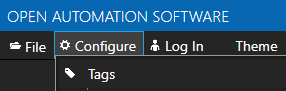
 Start Configure OAS application from the program group Open Automation Software.
Step 2
Select Configure-License and verify that CANBus is one of the available Drivers in the lower left of the form. If you do not CANBus driver available contact support@oasiot.com to update your license.
Note: You will need to be running Open Automation Software Version 8.0.0.10 or greater to support direct CANBus communications. You can download the latest version here.
Step 3
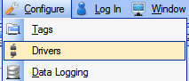
Select Configure-Drivers.
Step 4
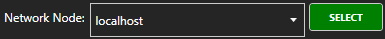
Select localhost or the remote service you wish to modify with the Select button to the right of the Network Node list.
![]()
Note: Optionally select the Live Data Cloud node if you are hosting CANBus data over the Internet with a standard Internet connection.
Step 5
Enter a meaningful Driver Interface Name that you will refer to this physical connection when defining Tags with a CANBus Data Source.
Define the properties for the desired physical connection.
Note: You may need to Set Default Network Adapter for Driver Interfaces of the operating system.
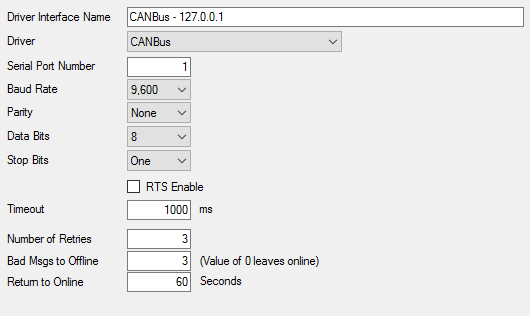
Note: Set the Driver to CANBus.
Step 6
Select the Add button in the lower part of the form to add the Driver Interface as an available selection when defining Tags in the next step.
![]()
Note: If you need to define several Driver Interfaces you can use the CSV Export and CSV Import on the toolbar in the upper right together with Microsoft Excel.
Step 7
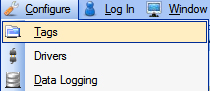
Select Configure-Tags.
Select localhost or the remote service you wish to modify with the Select button to the right of the Network Node list.
![]()
Note: Optionally select the Live Data Cloud node if you are hosting Modbus data over the Internet with a standard Internet connection.
Step 8
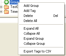
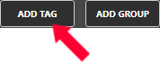
Select to Add a Tag.
Note: You can also add organizational Groups as many levels deep as you prefer and add tags to groups. To do this first add a Group to the root level, then right click on the Group in the right window to add additional Groups or Tags.
Step 9
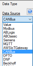
Change the Data Source Tag property to CANBus.
Step 10
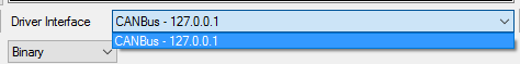
Select the correct Driver Interface from the Driver Interface pull down list.
Step 11
Specify the desired Polling Rate for the Tag.
Specify the Address of the variable to read and write to.
Step 12
To define multiple tags use the CSV Export and CSV Import on the toolbar in the upper right together with Microsoft Excel.
Note: You can also programmatically define Tags using the free to use OPC Systems component as demonstrated in the Form FormConfigureCSV in the WinForm Example Code application that installs with Open Automation Software in the Program Group Open Automation Software. This component can be used in any .NET application includes Web Services, Windows Services, WPF Applications, and ASP.NET or .NET MVC Web Applications.
Step 13
Select the Save button on the toolbar at the top.
![]()
Step 14
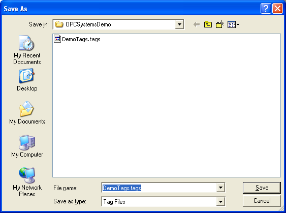
Create a directory on the local C: drive with the name OPCSystemsDemo.
Save the file DemoTags.tags in the directory C:OPCSystemsDemo.
Step 15
Under Configure – Options set the Default Tag Configuration File so when the computer restarts the tag file will automatically be loaded.
Getting Started – REST API
The following guide demonstrates how to connect to the OAS REST API.
To see how to use the OAS Platform with an external REST API view the Moving Data to an External REST API Use Case.
- 00:00 – Introduction
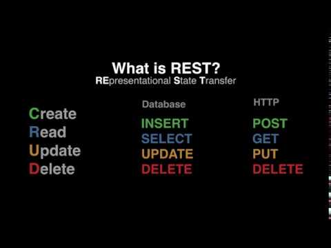
- 00:12 – What is REST API?
- 00:48 – What CRUD stands for?
- 00:52 – Database Terms for CRUD
- 01:00 – HTTP Parallel Methods
- 01:11 – Examples – Resources URLs
- 03:29 – What JSON stands for?
- 04:01 – Example – Difference between XML – JSON
- 04:22 – When to use OAS REST API
- 05:21 – REST Client Example Code
- 06:03 – Before using REST API
- 08:55 – REST Client Sample Code
- 10:03 – JavaScript
- 11:10 – Set HTTP Status
- 11:35 – Add Virtual Directory
- 12:12 – Sample Rest API Client
- 13:14 – Create a Tag List to Monitor
- 15:30 – Visual Studio
- 17:45 – Postman Application
- 21:08 – More Information
Step 1
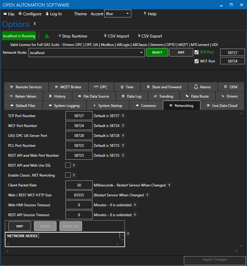
To use the OAS REST API you must make sure that the OAS HTTP service is listening on the correct port. This is done within the OAS Configuration application.
Open the OAS Configuration application and select Configure > Options, then select the network node (localhost if working on the local machine) and click Select.
Under the Networking tab, locate the field for REST API/WebHMI Port Number. The default is 58725 but can be changed. If you are accessing the server from a remote client, you will also need to make sure your machine and/or company firewalls allow TCP traffic on the selected port.
Using SSL with REST API is fully supported.
Read more about Configuring OAS to use SSL for Web and REST API products.
NOTE: Making any changes to the port numbers in this section of the configuration app will temporarily restart server processes and may cause a brief interruption in data processing.
Step 2
Install Postman
Navigate to https://restapi.openautomationsoftware.com to open the REST API online documentation.
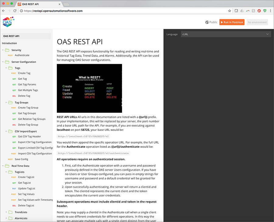
This documentation illustrates all of the operations available to any REST API client and can be tested using the Postman application client. In the upper right corner of the documentation, you will see a button to Run in Postman, which will install the API documentation into the Postman client for direct execution against any OAS server. Additionally, the documentation can be configured to display code samples in multiple languages including cURL, jQuery, and NodeJS. Feel free to browse the documentation at any time and to refer back to it while developing your applications.
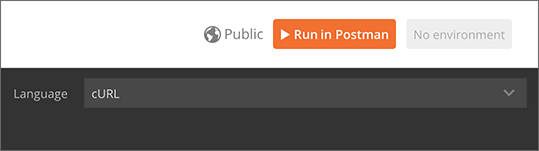
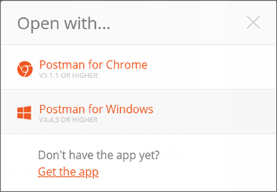
Clicking Run in Postman will pop up a dialog box to import the REST API into an existing installation of Postman, or you can choose to install the app for the first time. Postman is available for Windows and Mac desktops as well as in a Chrome extension.
Step 3
Test your API installation
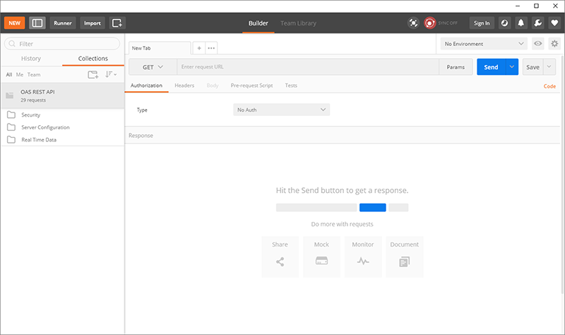
Once installed and the API has been downloaded into the app, you will see the following interface, with all operations on the left, organized identically to the online documentation:
The first operation to execute is the Authenticate call, which will generate a REST API session and returns a clientid and token to be used in all subsequent calls to the OAS server.
In the list of operations, expand and select Authenticate and you will see the following on the right side of the app:
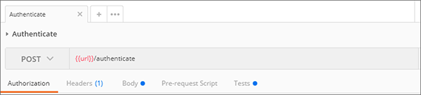
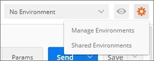
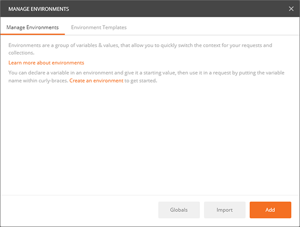
This shows that the Authenticate operation is executed as an HTTP POST against the /authenticate URL appended to the base {{url}}. This base URL is defined in your Environment here. Select Manage Environments to add new fields:
Add your server to the Environments list
Click ADD to create a new Environment which will hold environment variables:
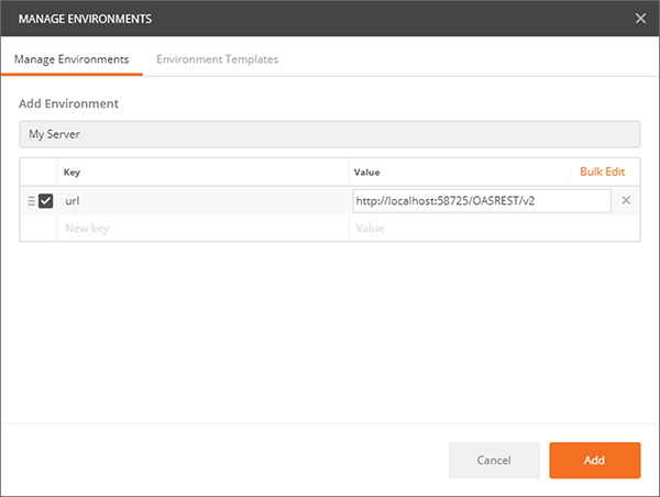
Add a name for your environment, then add a key of url with a value of http://localhost:58725/OASREST/v2 and click ADD to create the new environment. You can also use your OAS server’s IP address instead of localhost, if you are connecting to it from a remote workstation.
Next, return to execute the the Authenticate operation.
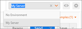
Now under the Environments dropdown, select your new Environment. You should see the {{url}} turn orange, indicating that the environment variable is being used.
You can now click SEND to execute the post against your server. If successful, you should see a response body similar to the one below, containing the clientid and token fields.
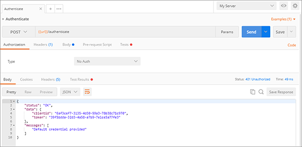
You can then use these fields in the header of all other operations using the Postman app to test your server.
Step 4
Accessing Tag Values
Once authenticated, you are now able to use the clientid and token in HTTP headers to make calls to configure Tags, access real time and historical Tag data, and even real time and historical Alarm and Trend data. When referencing Tags in any call, you it is assumed that you are accessing them on the OAS server being called in the REST API. However, you can also access remote Tags on any OAS server networked with the target server. Read more about the proper syntax for accessing Tags and Tag Variables.
Remote Access
OAS servers can communicate with each other and pass along tag data. This allows for distributed network load as well as placing OAS servers behind firewalls so they cannot be accessed directly. This allows you to securely issue REST API calls against one server and read/write data within a remote OAS server that cannot be reached directly from the REST API client. This same concept applies whether you are calling the OAS REST API or using the .NET Data Connector for programmatic Tag access and configuration.
- Main OAS Engine : the server handling the REST API calls
- Remote OAS Engine : the server housing the tag data or configuration you would like to access
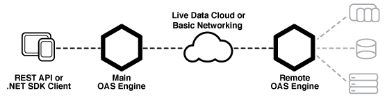
REST API URL
Set the url to OAS Engine that the REST API will be hosted from. This is the URL to the Main OAS Engine whether you are accessing tag data on the Main OAS Engine or on a Remote OAS Engine.
Localhost URL : will only work when accessing the Main OAS Engine on the same machine as the client.
http://localhost:58725/OASREST/v2
Explicit URL : use the IP Address or domain name of the Main OAS Engine, allowing you to access it from a remote client. This will also work on the same machine and is the best option for code flexibility.
http://192.168.0.1:58725/OASREST/v2
Tag Access
Main OAS Engine Tag – accessing tag data on the Main OAS Engine only requires referencing the tag path.
{
    "tags": [
      {"path":"TagName.Value"}
    ]
}
Remote OAS Engine Tag – To monitor real time data from Remote OAS Engines reference the tag path in the form \\<Remote OAS address>\<Tag Path>. Note in the example below that backslash characters are escaped within strings, changing \ to \\ and \\ to \\\\.
Basic Networking – Static IP or domain name
{
    "tags": [
      {"path":"\\\\192.168.0.2\\TagName.Value"},
      {"path":"\\\\192.168.0.3\\TagName.Value"},
      {"path":"\\\\myserver.com\\TagName.Value"}
    ]
}
Live Data Cloud Networking – Dynamic IP
Once you have registered named Live Data Cloud nodes on an OAS server, you can reference them in the form RemoteSCADAHosting.<Node Name>.<Tag Path>.
{
    "tags": [
      {"path":"RemoteSCADAHosting.LiveDataCloudNode01.TagName.Value"},
      {"path":"RemoteSCADAHosting.LiveDataCloudNode02.TagName.Value"},
      {"path":"RemoteSCADAHosting.LiveDataCloudNode03.TagName.Value"}
    ]
}
Remote Configuration Calls
To execute REST API Tag Configuration calls against Remote OAS Engines, you can use the networknode parameter to reference a static IP or domain name, or the ldc parameter to reference a Live Data Cloud node name. The example below demonstrates calls to the CSV Tag configuration calls using each of these methods.
Basic Networking – Static IP or domain name
http://192.168.0.1:58725/OASREST/v2/csvtags?columns=Tag,Value - Data Type,Value - Value,Last Column&networknode=192.168.0.2
Live Data Cloud Networking – Dynamic IP
http://192.168.0.1:58725/OASREST/v2/csvtags?columns=Tag,Value - Data Type,Value - Value,Last Column&ldc=LiveDataCloudNode01
Remote Security
Because your authentication call is always against the Main OAS Engine, that same credential will be passed to any networked OAS Engine when referencing remote Tags. So it is critical to make sure the same credential (username/password) exists on all networked OAS Engines and has been granted the appropriate access level for the command being executed.
Getting Started OPC UA
OAS is both an OPC UA Client and OPC UA Server.
If you want interface OAS with an OPC UA Client please see the Getting Started OPC UA Client guide.
Open Automation Software Tags can be defined to connect to OPC UA Servers with the built in OPC UA Driver Interface.

The following steps can be used to setup communications with OPC UA Servers.
Step 1 – Check OPC UA License
Start Configure OAS application from the program group Open Automation Software.
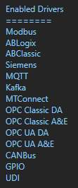
Select Configure-License and verify that OPC UA is one of the available Drivers in the lower left of the window. If you do not see OPC UA available contact support@oasiot.com to update your license.
NOTE: To configure remote OAS Engines enter the IP Address or node name in the Network Node field and click on Select.
NOTE: You will need to be running Open Automation Software Version 10.0.0.12 or greater to support OPC UA communications. You can download the latest version from our Open Automation Software Download page.
Step 2 – Configure OPC UA Driver
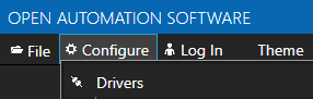
Select Configure-Drivers.
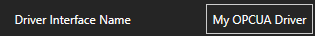
Enter a meaningful Driver Interface Name that you will refer to this physical connection when defining Tags with an OPC UA Data Source.
Set the Driver type to OPC UA.
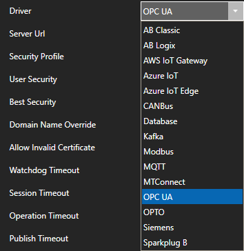
Define the Server Url property to the endpoint of the OPC UA server to connect to.

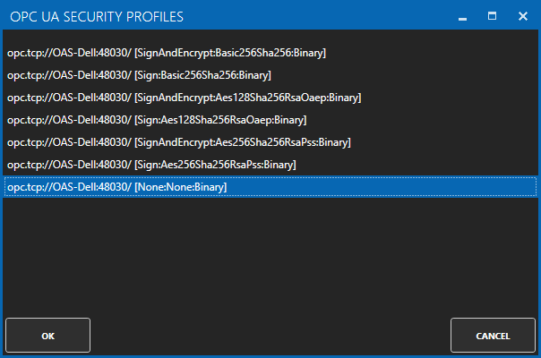
Use the BROWSE button of the Security Profile to select one of the security profiles. Use None:None:Binary for the fastest interface.

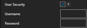
If the server requires user authentication enable the property User Security to define the Username and Password.
Optionally define a secondary failover server if the primary server fails with the property Enable Failover.
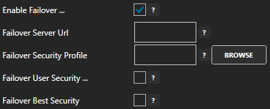
If both the primary and secondary servers are offline the Return to Online settings determines the retry frequency.
View Driver Interface Failover for more information and and video demonstrating communications failover.
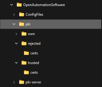
NOTE: The certificate path is C:\ProgramData\OpenAutomationSoftware\pki on Windows and /ConfigFiles/pki/ on Linux. You may need to move the server’s certificate from the rejected\certs folder to the trusted\certs folder.
Select the Add Driver button in the upper left of the window to add the Driver Interface as an available selection when defining Tags in the next step.

Note: If you need to define several Driver Interfaces you can use the CSV Export and CSV Import on the toolbar together with Microsoft Excel.
Drivers can also be programmatically assigned with the OAS REST API or .NET Server Configuration interface.
Step 3 – Configure OPC UA Tags
Select Configure-Tags.
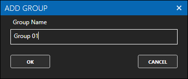
Select Add Group to add a group to place tags in.
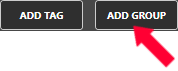
NOTE: You can add organizational Groups as many levels deep as you prefer and add tags to groups. To do this first add a Group to the root level, then right click on the Group in the right window to add additional Groups or Tags.
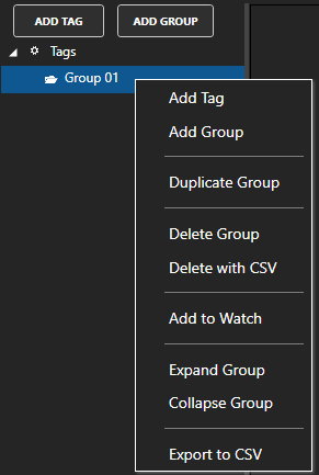
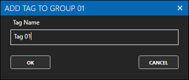
Select Add Tag to add a tag to the group selected.
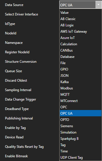
Change the Data Source property to OPC UA.
If you have more than one OPC UA Server defined in the Driver Interfaces select the desired Driver Interface.
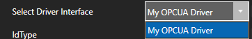
Use the BROWSE button next to the NodeId to browse for a node in the OPC UA server.

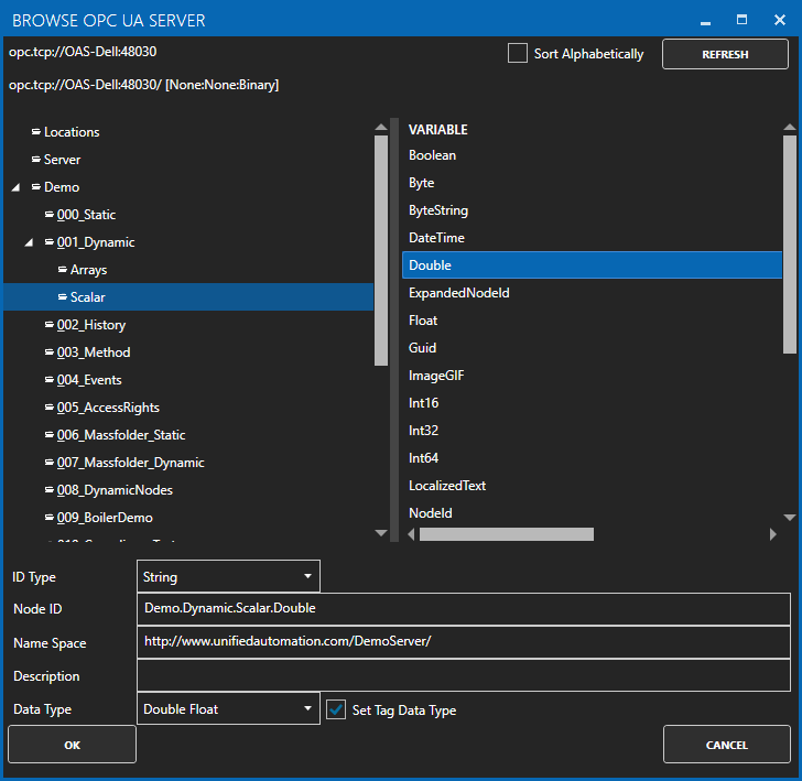
Select OK to assign the IdType, NodeId, Namespace, and Data Type.
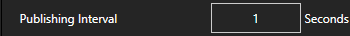
Specify the desired Publishing Interval for the Tag.
Select Apply Changes and verify the Value and data quality is good.

Check that the data quality of the tag is Good Quality and the value from the OPC UA server is returned.

NOTE: If you are unable to connect to the OPC UA Server due to a certificate security error go to C:\ProgramData\OpenAutomationSoftware\pki\ on Windows or the pki sub-directory where the OAS Engine is located on Linux and copy the files in the rejected\certs directory to trusted\certs.
If the data quality is ![]() view Troubleshooting OPC UA Server Connection Error for solutions to common errors.
view Troubleshooting OPC UA Server Connection Error for solutions to common errors.
To define multiple tags use one of the following optional methods.
- Use One Click OPC UA to automatically create tags from all OPC UA Nodes from a selected OPC Server or branch within an OPC Server. Then selectively delete the groups and tags that are not required.
- Use CSV Export and CSV Import on the toolbar in the upper right together with Microsoft Excel to add or modify tags.
- Programmatically define Tags using the free to use OASConfig component with the SetTagProperties method.
- Programmatically define Tags with the OAS REST API.
Step 4 – Save OPC UA Tags and Drivers
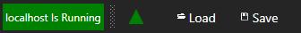
Select the Save button on the toolbar at the top.
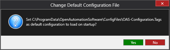
Enter a file name to be saved in C:\ProgramData\OpenAutomationSoftware\ConfigFiles directory on Windows or ConfigFiles subdirectory on Linux.
When prompted to set the file as the default configuration to load on startup select Yes.
NOTE: The tags and and drivers are both saved into one file.
The tags defined are now ready for use in all OAS features like Data Logging, Data Route, and Open UIEngine.