The following list provides a reference of all Tag Configuration Properties.
Each property name is listed using three different formats.
The third format is use by the OAS Engine when referencing Tag properties in configuration settings that require Tag path references and calculations. Not all configuration properties are exposed in the OAS Engine as Tag properties.
| Properties |
Description |
Value – Data Type
Value_Data_Type
DataType |
The data type of a Parameter can be set To one of the following types.
Double Float (64 bit)
Single Float (32 bit)
Signed Byte (8 bit)
Unsigned Byte (8 bit)
Short Integer (16 bit)
Unsigned Short Integer (16 bit)
Integer (32 bit)
Unsigned Integer (32 bit)
Long Integer (64 bit)
Unsigned Long Integer (64 bit)
Boolean
String
JSON
Array Double (64 bit)
Array Single (32 bit)
Array Integer (32 bit)
Array Byte (8 bit)
Array Boolean
Array String
Object Type (Any value, custom Object, array, Or Structure)
[Double Float, Single Float, SByte, Byte, Short Integer, Unsigned Short Integer, Integer, Unsigned
Integer, Long Integer, Unsigned Long Integer, Boolean, String, JSON, Array Double Float, Array Single Float,
Array Integer, Array Byte, Array Boolean, Array String, Object]
|
Value – Value
Value_Value
Value |
Enter the desired value when the Data Source is set to Value. |
Value – Trim At First Null
Value_Trim_At_First_Null
TrimAtFirstNull |
When enabled all characters after the first null character are removed from the string value.
A useful feature for null terminated strings.
Requires a new value update from the source to process.
All null characters are removed from the string value regardless of this setting.
|
Value – Enable Bitmask
Value_Enable_Bitmask
EnableBitmask |
When enabled a Bitmask is applied on the source value.
Examples:
Source value 255, Bitmask is F, result is 15.
Source value 255, Bitmask is 1F, result is 31.
When writing to the tag the Bitmask is not used.
|
Value – Bitmask
Value_Bitmask
Bitmask |
Bitmask to apply to source value when data type is an integer.
Valid range is 0 to FFFFFFFFFFFFFFFF
Examples:
Source value 255, Bitmask is F, result is 15.
Source value 255, Bitmask is 1F, result is 31.
When writing to the tag the Bitmask is not used.
|
Value – Bitmask Compress
Value_Bitmask_Compress
BitmaskCompress |
When enabled a Bitmask that is applied compresses the masked bits to only the bit patter in the mask.
Examples:
Source value 238535, bits 101110100011011
Bitmask F – result is 11, bits 1011
Bitmask C – result is 2, bits 10
Bitmask C000 – result is 1, bit 1
Bitmask FF00 – result is 93, bits 1011101
Bitmask AAAA – result is 35, bits 0100011
When writing to the tag the Bitmask is not used.
|
Value – Gain
Value_Gain
Gain |
The Gain is a multiplier to the raw incoming value except when the Data Source is Value:
Value = RawValue * Gain + Offset
When writing to an item the calculation is reversed:
OutputValue = (Value – Offset) / Gain
|
Value – Offset
Value_Offset
Offset |
The Offset is an addition to the raw incoming value except when the Data Source is Value:
Value = RawValue * Gain + Offset
When writing to an item the calculation is reversed:
OutputValue = (Value – Offset) / Gain
|
Value – High Range
Value_High_Range
HighRange |
The Default Y Axis Range High For a trend pen and the high limit when Limit Writes is enabled. |
Value – Low Range
Value_Low_Range
LowRange |
The Default Y Axis Range Low For a trend pen and the low limit when Limit Writes is enabled. |
Value – Limit Writes
Value_Limit_Writes
LimitWrites |
Limit writes from users and clients within the High Range and Low Range. |
Value – Read Only Value
Value_Read_Only_Value
ReadOnlyValue |
When enabled the value of the parameter cannot be written to. |
Value – Write Only Value
Value_Write_Only_Value
WriteOnlyValue |
When enabled the value of the parameter will not be read from the source but will allow writes. |
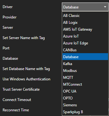
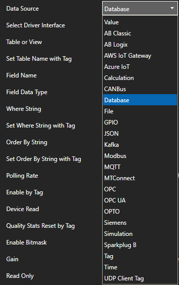
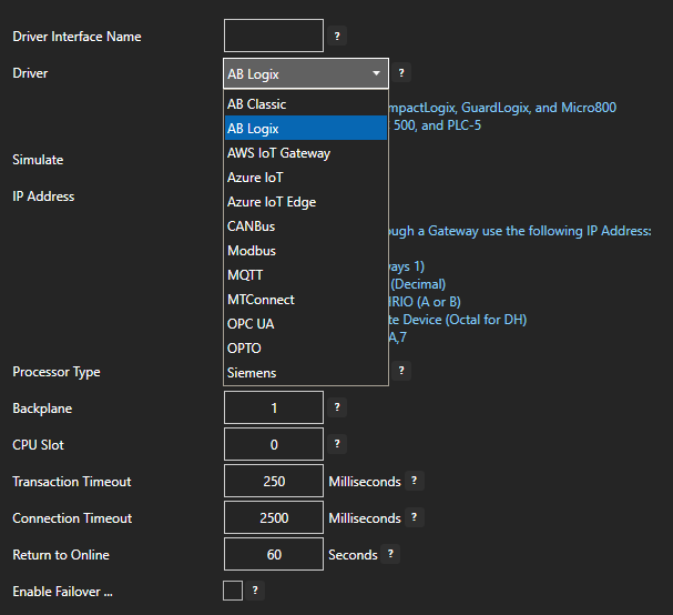
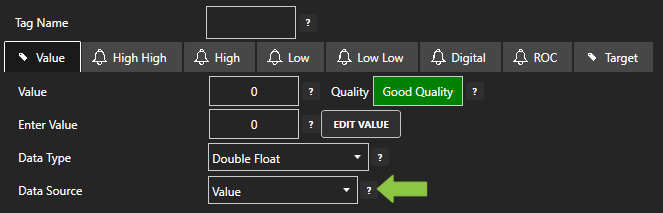
Value – Source
Value_Source
DataSource |
The source Of where the value will come from. The Data Source can be Set To one Of the following types:
Value: Fixed value that can be set in configuration or from any client.
AB Classic: Communications to Allen Bradley MicroLogix, SLC 500, and PLC-5.
AB Logix: Communications to Allen Bradley ControlLogix, CompactLogix, GuardLogix, and Micro800.
AWS IoT Gateway: Amazon Web Services IoT Gateway.
Azure IoT: Azure IoT Data Hub.
Calculation: Math equation with multiple tag parameters as a data source. The result is read only and
cannot be written to. View the following video to see how to define a Calculation.
CanBus: CanBus interface
File: A Binary, Text, or XML file.
GPIO: General Purpose Input Output for Raspberry Pi.
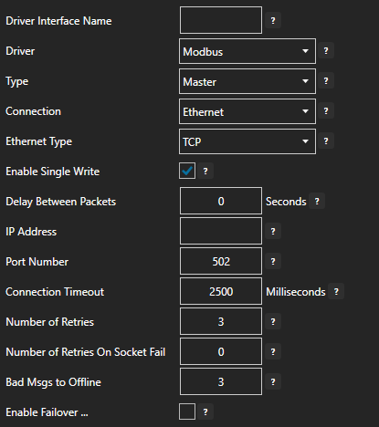
Modbus: Modbus master communications for Modbus TCP, Modbus RTU, and Modbus ASCII all supported on
both Ethernet and Serial interfaces.
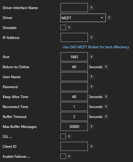
MQTT: Communications to MQTT brokers to send and receive data to MQTT devices and software.
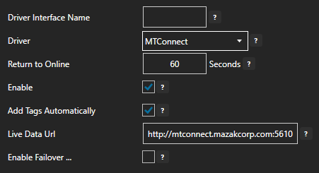
MTConnect: Automated tag creation and live value update from MTConnect.
OPC: Value from Classic DA 2.XX or 3.0 OPC Server.
OPC UA: OPC UA Server.
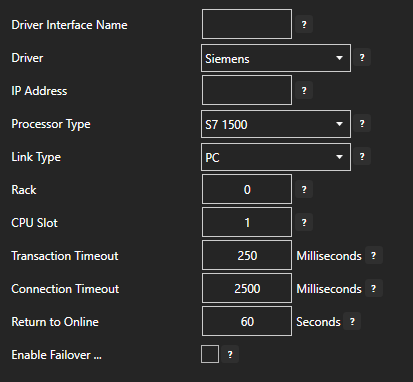
Siemens: Communications to Siemens S7-200, S7-300, S7-400, S7-1200, and S7-1500.
Simulation: Dynamic simulation of data.
Tag: Value is from another tag parameter from the same service or remote service. The result is read
only and cannot be written to.
Time: Date and time from the CPU clock.
UDP Client Tag: Tag from a remote service with the UDP Broadcast feature enabled.
Univeral Driver Interfaces will also appear here in the Data Source property
|
Value – Simulation Rate
Value_Simulation_Rate
SimulationRate |
The rate of value changing for Simulation data. |
Value – Simulation Type
Value_Simulation_Type
SimulationType |
Ramp will incrment in value from 0 to 99.
Sine will change value from -1 to 1 based on the time each 60 seconds.
Random will result in a random number with a range of 0 to 99
Toggle will transition between true and false
[Ramp, Random, Sine, Toggle]
|
Value – OPC Item
Value_OPC_Item
OPCItem |
Set the OPC Item from a classic OPC DA Server. |
Value – Tag Client Item
Value_Tag_Client_Item
Tag |
Specify a local or remote Tag To receive the value from when the Data Source is set to Tag. |
Value – UDP Client Item
Value_UDP_Client_Item
UDPClientTag |
The Tag in the broadcasting service to receive the value when using one way UDP Broadcast feature. |
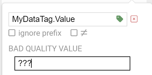
Value – Source Values On Bad
Quality
Value_Source_Values_On_Bad_Quality
SourceWhenBad |
Allows the value and data quality to be overridden when the value quality is bad.
The following are the four (4) available options for Source When Bad:
Normal Bad Quality: When the data source is bad quality the result is bad quality. With Calculations
any one of the source tags in the calculation being bad quality will cause the result to be bad quality.
Set Sources To Default Value: When the data source quality is bad the source value is overridden to be
what is set as Default Value with the data type of Default Value Type. With Calculations that have multiple
tag parameters as a source each individual tag value in the calculation will be set to the Default Value
when its individual data quality is bad. This will result in the calculation performing the equation with
the remaining actual values with tags with good quality and overriding the values for the tags that are bad
quality.
Hold Sources To Last Good Value: When the data sources quality changes to bad quality the last good
value will be used as the data source. With Calculations that have multiple tag parameters as a source each
individual tag value in the calculation will be held with its last good value when its individual data
quality is bad. This will result in the calculation performing the equation with remaining actual values
with tags with good quality and overriding the values for the tags that are bad quality with each individual
tags last good quality.
Set Sources To Tag Value: When the data sources quality is bad the value from another Tag will be
used. With Calculations that have multiple tag parameters as a source each individual tag value in the
calculation will be set from the other Tag value. This will result in the calculation performing the
equation with remaining actual values with tags with good quality and overriding the values for the tags
that are bad quality with the assigned tag’s value
[Normal Bad Quality, Set Sources To Default Value, Hold Sources To Last Good Value, Set Sources To Tag
Value]
|
Value – Override OPC Quality On Bad
Quality
Value_Override_OPC_Quality_On_Bad_Quality
OverrideOPCQualityWhenBad |
Forces the OPC Quality that is passed onto the OPC Systems.NET OPC Server to good quality when the Data
Source When Bad Quality is set to something other than the default of Normal Bad Quality and the Data Source
is set to an OPC Item. |
Value – Default Value Type On Bad
Quality
Value_Default_Value_Type_On_Bad_Quality
DefaultValueDataTypeWhenBad |
The data type to use when the Source When Bad is set to Set Sources to Default Value. See Source When Bad
for full description.
[Double Float, Single Float, SByte, Byte, Short Integer, Unsigned Short Integer, Integer, Unsigned
Integer, Long Integer, Unsigned Long Integer, Boolean, String, Object]
|
Value – Default Value On Bad
Quality
Value_Default_Value_On_Bad_Quality
DefaultValueWhenBad |
The value to use when the Source When Bad is set to Set Sources to Default Value. See Source When Bad for
full description. |
Value – Tag For Source On Bad Quality
Value_Tag_For_Source_On_Bad_Quality
|
When Source When Bad is set to Set Sources To Tag Value this is the tag parameter to use for the value to
set the source when the data quality is bad. |
Value – Is Trend Point
Value_Is_Trend_Point
TrendPoint |
Enable Trend Point to have the Parameter available for trending from Trend .NET and Web Trend. You can data
log a Parameter value without trending the point If desired. |
Value – Desc
Value_Desc
Description |
Description of the Tag used as the default Trend Pen Description.
Also used as the default Alarm Text when an Alarm Limit is first enabled.
|
Value – Units
Value_Units
Units |
Engineering Units of the Tag used as the default Trend Pen Units. |
Value – Document
Value_Document
Document |
The document path that is included in an alarm message. |
Value – TagID
Value_TagID
TagID |
Identifier for OEM asset assignment. |
Value – OPC Update Rate
Value_OPC_Update_Rate
OPCUpdateRate |
OPC Update Rate. Each unique rate creates an individual Group In the Server For subscription. |
Value – OPC Access Path
Value_OPC_Access_Path
|
Set the OPC Access Path from a classic OPC DA Server. Most OPC Servers Do Not require an Access Path. It is
very rare that the OPC Server needs this Property. |
Value – OPC Enumerated
Value_OPC_Enumerated
OPCEnumerate |
When enabled it will convert the integer value to the text from the item within the enumeration. |
Value – OPC Enumerated Values
Value_OPC_Enumerated_Values
OPCEnumerateStrings
|
The list of enumerations to return based on integer value for the index. The string arrays are separated by
a pipe character. |
Value – Use Enumerated Index
Value_Use_Enumerated_Index
|
If the integer value for OPC Enumerate does not begin with 0 or is not continuous numbers to convert to the
string array for OPC Enumerate you can enable Enumerate Index to provide an index array of integer values to
convert to. |
Value – Enumerated Index
Value_Enumerated_Index
|
If the integer value for OPC Enumerate does not begin with 0 or is not continuous numbers to convert to the
string array for OPC Enumerate you can enable Enumerate Index to provide an index array of integer values to
convert to. |
Value – Keep OPC Item On Scan
Value_Keep_OPC_Item_On_Scan
OPCItemKeepOnScan |
With this Option selected the communications To the OPC Item will always be enabled unless the Device Read
Option is selected.
When this Option is disabled communications To the OPC Item will be enabled only When one Or more
clients are requesting the value from the Tag. If the point is trended, enabled For alarm monitoring With
any one Of the alarm limits enabled, Or Set As a Target output To another OPC Item this OPC Item will always
be On scan regardless If there is a requesting client.
Note: Not recommended for OPC Items from RS-Linx OPC Server as it does not handle dynamic adding and
removing items well.
|
Value – Enable Device Read
Value_Enable_Device_Read
OPCDeviceRead |
When enabled the Tag defined For the Device Read will control communications To only read the OPC Item With
a SyncRead When the tag transitions from False To True. Normal asynchronous communications is disabled If
this Property is enabled. |
Value – Device Read Tag
Value_Device_Read_Tag
OPCDeviceReadTag |
The Tag that will cause a syncread To the OPC Item When the value transitions from False To True. |
Value – OPC Enable Comm
Value_OPC_Enable_Comm
|
Enable Or Disable OPC Classic communications based On a Tag. When the value Of the Tag defined is True the
communications To the OPC Item is enabled, When False it is disabled. |
Value – OPC Enable Comm Tag
Value_OPC_Enable_Comm_Tag
|
The Tag that will enable Or disable communications To the OPC Item When the Enable by Tag Property is
enabled. |
Value – Driver Interface
Value_Driver_Interface
|
Set the defined Driver Interface for the Data Source selected. |
Value – Driver Interface Polling Rate
Value_Driver_Interface_Polling_Rate
|
Polling rate for Driver Interface item. |
Value – Driver Interface Keep Item On
Scan
Value_Driver_Interface_Keep_Item_On_Scan
|
With this option selected the communications to the Item will always be enabled unless the Device Read
option is selected.
When this option is disabled communications to the Item will be enabled only when one or more clients
are requesting the value from the Tag. If the point is trended, enabled for alarm monitoring with any one of
the alarm limits enabled, or set as a Target output to another OPC Item this OPC Item will always be on scan
regardless if there is a requesting client.
|
Value – Driver Interface Enable Device
Read
Value_Driver_Interface_Enable_Device_Read
|
When enabled the Tag defined for the Device Read will control communications to only read the item with when
the tag transitions from false to true. Normal polling communications is disabled if this property is
enabled. |
Value – Driver Interface Device Read Tag
Value_Driver_Interface_Device_Read_Tag
|
The Tag that will cause a read for the item when the value transitions from false to true if Device Read is
enabled. |
Value – Driver Interface Enable Comm
Value_Driver_Interface_Enable_Comm
|
Enable or Disable communications based on a Tag. When the value of the Tag defined is true the
communications to the Item is enabled, when false it is disabled. |
Value – Driver Interface Enable Comm Tag
Value_Driver_Interface_Enable_Comm_Tag
|
The Tag that will enable or disable communications to the OPC Item when the Enable by Tag property is
enabled. |
Value – Quality Stats Reset By Tag
Value_Quality_Stats_Reset_By_Tag
|
Enable or Disable communications statistics based on a Tag. When the value of the Tag defined transitions
from false to true the communications statistics for the tag are reset. |
Value – Quality Stats Reset Tag
Value_Quality_Stats_Reset_Tag
|
The Tag that will reset the communications statistics when the value transitions from false to true. |
Value – MTConnect Data Type
Value_MTConnect_Data_Type
|
The data type of a Parameter can be set to one of the following types.
DataItem: Adds 13 additional parameters.
|
Value – MTConnect Id
Value_MTConnect_Id
|
The unique identifier for this DataItem. The id attribute MUST be unique across the entire document
including the ids for components. An XML ID-type. |
Value – MTConnect Name
Value_MTConnect_Name
|
The name of the DataItem. A name is provided as an additional human readable identifier for this DataItem in
addition to the id. It is not required and will be implementation dependent. An NMTOKEN XML type. |
Value – MTConnect Type
Value_MTConnect_Type
|
The type of data being measured. Examples of types are POSITION, VELOCITY, ANGLE, BLOCK, ROTARY_VELOCITY,
etc. |
Value – MTConnect Sub Type
Value_MTConnect_Sub_Type
|
A sub-categorization of the data item type. For example, the subtypes of POSITION are ACTUAL and COMMANDED.
Not all types have subtypes and this can be left off. |
Value – MTConnect Category
Value_MTConnect_Category
|
This is how the meaning of the data item will be determined. The available options are SAMPLE, EVENT, or
CONDITION. |
Value – MTConnect Statistic
Value_MTConnect_Statistic
|
Data calculated specific to a DataItem. Examples of statistic are AVERAGE, MINIMUM, MAXIMUM,
ROOT_MEAN_SQUARE, RANGE, MEDIAN, MODE, AND STANDARD_DEVIATION. |
Value – MTConnect Representation
Value_MTConnect_Representation
|
Data consisting of multiple data points or samples or a file presented as a single DataItem. Each
representation will have a unique format defined for each representation. Examples of representation are
VALUE, TIME_SERIES, MP3, WAV, etc. Initially, the representation for TIME_SERIES and VALUE are defined. If a
representation is not specified, it MUST be determined to be VALUE. |
Value – MTConnect Native Units
Value_MTConnect_Native_Units
|
The native units used by the Component. These units will be converted before they are delivered to the
application. |
Value – MTConnect Units
Value_MTConnect_Units
|
Units MUST be present for all samples. If the data represented by a DataItem is a numeric value, except for
line number and count, the units MUST be specified. |
Value – MTConnect Native Scale
Value_MTConnect_Native_Scale
|
The multiplier for the native units. The received data MAY be divided by this value before conversion. If
provided, the value MUST be numeric. |
Value – MTConnect Significant Digits
Value_MTConnect_Significant_Digits
|
The number of significant digits in the reported value. This is used by applications to determine accuracy
of values. This SHOULD be specified for all numeric values. |
Value – MTConnect Sample Rate
Value_MTConnect_Sample_Rate
|
The rate at which successive samples of a DataItem are recorded. SampleRate is expressed in terms of samples
per second. If the sample rate is smaller than one, the number can be represented as a floating point
number. For example, a rate 1 per 10 seconds would be 0.1. |
Value – MTConnect Coordinate System
Value_MTConnect_Coordinate_System
|
The coordinate system being used. The available values for coordinateSystem is WORK and MACHINE. |
Value – Table Name
Value_Table_Name
|
The Table Name or View to use when Data Source is set to Database. |
Value – Use Tag Value For Table Name
Value_Use_Tag_Value_For_Table_Name
|
When enabled the table name can be dynamically set with a Tag Parameter value. |
Value – Tag For Table Name
Value_Use_Tag_Value_For_Table_Name
|
When enabled the table name can be dynamically set with a Tag Parameter value. |
Value – Field Name
Value_Field_Name
|
The column name to read the value from or write the value to. |
Value – Field Data Type
Value_Field_Data_Type
|
The data type of the field. |
Value – Where String
Value_Where_String
|
The filter condition to specify which row to read and update. When writing values all row matching where
statement will be updated. |
Value – Use Tag Value For Where String
Value_Use_Tag_Value_For_Where_String
|
When enabled the Where String can be dynamically set with a Tag Parameter value. |
Value – Tag For Where String
Value_Tag_For_Where_String
|
When enabled the Where String can be dynamically set with a Tag Parameter value. |
Value – Order By String
Value_Order_By_String
|
The condition order the records to use top 1 when reading. |
Value – Use Tag Value For Order By
String
Value_Use_Tag_Value_For_Order_By_String
|
When enabled the Order By String can be dynamically set with a Tag Parameter value. |
Value – Tag For Order By String
Value_Tag_For_Order_By_String
|
When enabled the Order By String can be dynamically set with a Tag Parameter value. |
Value – Modbus Memory Type
Value_Modbus_Memory_Type
|
Modbus Memory Type.
[Coil Status, Input Status, Holding Register, Input Register]
|
Value – Modbus Device Address
Value_Modbus_Device_Address
|
Modbus Device Address. Set To -1 To Not use Device Address With Ethernet. |
Value – Modbus Data Type
Value_Modbus_Data_Type
|
Modbus Data Type
[Int16, UInt16, Int16 As Boolean, Int32, UInt32, Int32 As Boolean, Int64, UInt64, Int64 As Boolean,
Float32, Float64, String]
|
Value – Modbus Address
Value_Modbus_Address
|
Modbus address Of point. Use Zero Based Addressing to offset the address by 1.
The Memory Type selected will automatically add the necessary base address. For example to address
40,000 set the Memory Type to Holding Register and the Address as 1.
Extended Addressing is also supported.
|
Value – Modbus Bit Position
Value_Modbus_Bit_Position
|
Bit position within Integer. |
Value – Modbus Number Of Words For
String
Value_Modbus_Number_Of_Words_For_String
|
The length Of the Modbus String When the Modbus Data Type is set to String. |
Value – Modbus Max Words Per Packet
Value_Modbus_Max_Words_Per_Packet
|
The maximum number Of words per packet In communications. The Driver Interface will use the lowest number As
the limit For all communications For all packets. |
Value – Modbus Max Bits Per Packet
Value_Modbus_Max_Bits_Per_Packet
|
The maximum number of bits per packet when Memory Type is set to either Coil Status or Input Status. |
Value – Modbus Word Swap
Value_Modbus_Word_Swap
|
Swaps Modbus words. |
Value – Modbus Byte Swap
Value_Modbus_Byte_Swap
|
Swaps Modbus bytes. |
Value – Modbus Zero Based Addressing
Value_Modbus_Zero_Based_Addressing
|
When enabled subtracts 1 from address before communicating To device. |
Value – CANBus Block Number
Value_CANBus_Block_Number
|
CANBus Block Number. |
Value – CANBus Index
Value_CANBus_Index
|
CANBus Index. |
Value – CANBus Block Type
Value_CANBus_Block_Type
|
Block Type For CANBus. |
Value – OPTO Value Type
Value_OPTO_Value_Type
|
OPTO Value Type. Use Table Elements For the fastest communications.
[Table, TableElement, Variable]
|
Value – OPTO Variable Name
Value_OPTO_Variable_Name
|
OPTO Variable Name. |
Value – OPTO Variable Type
Value_OPTO_Variable_Type
|
OPTO Variable Data Type.
[Integer32Bit, Integer64Bit, Float32Bit, StringVariable, UpTimer, DownTimer]
|
Value – OPTO Variable String Length
Value_OPTO_Variable_String_Length
|
OPTO Variable String Length. |
Value – OPTO Table Name
Value_OPTO_Table_Name
|
OPTO Table Name. |
Value – OPTO Table Type
Value_OPTO_Table_Type
|
OPTO Table Data Type.
[Integer32Bit, Integer64Bit, Float32Bit, StringVariable]
|
Value – OPTO Table String Length
Value_OPTO_Table_String_Length
|
OPTO Table String Length. |
Value – OPTO Table Index
Value_OPTO_Table_Index
|
OPTO Table Index. |
Value – OPTO Table Length
Value_OPTO_Table_Length
|
OPTO Table Length. |
Value – AB Logix Data Type
Value_AB_Logix_Data_Type
|
Data Type For AB Logix. Use AUTO If you are uncertain Of your data type.
[AUTO, STR]
|
Value – AB Address
Value_AB_Address
ABAddress |
The Allen Bradley variable address. |
Value – Siemens Address
Value_Siemens_Address
SiemensAddress |
The Siemens variable address. See https://openautomationsoftware.com/knowledge-base/siemens-address-syntax/
Data Sources-Siemens-Siemens Address Syntax For address syntax. |
Value – Siemens Data Type
Value_Siemens_Data_Type
|
Data Type For Siemens. |
Value – Siemens String Length
Value_Siemens_String_Length
|
The length Of the Siemens String When the Siemens Data Type is set to String. |
Value – Array Length
Value_Array_Length
|
The length Of the Array. |
Value – Kafka Topic
Value_Kafka_Topic
|
Kafka Topic. |
Value – SpB Client Group ID
Value_SpB_Client_Group_ID
|
Sparkplug B Client Group ID. |
Value – SpB Client Edge Node ID
Value_SpB_Client_Edge_Node_ID
|
Sparkplug B Client Edge Node ID. |
Value – SpB Client Device ID
Value_SpB_Client_Device_ID
|
Sparkplug B Client Device ID. |
Value – SpB Client Metric Name
Value_SpB_Client_Metric_Name
|
Sparkplug B Client Metric Name. |
Value – SpB Host Group ID
Value_SpB_Host_Group_ID
|
Sparkplug B Host Group ID.
Used for Tag Publish feature in Driver Interface and OAS MQTT Broker.
|
Value – SpB Host Edge Node ID
Value_SpB_Host_Edge_Node_ID
|
Sparkplug B Host Edge Node ID.
Used for Tag Publish feature in Driver Interface and OAS MQTT Broker.
|
Value – SpB Host Device ID
Value_SpB_Host_Device_ID
|
Sparkplug B Host Device ID.
Used for Tag Publish feature in Driver Interface and OAS MQTT Broker.
|
Value – SpB Host Metric Name
Value_SpB_Host_Metric_Name
|
Sparkplug B Host Metric Name.
Used for Tag Publish feature in Driver Interface and OAS MQTT Broker.
|
Value – MQTT Topic
Value_MQTT_Topic
|
MQTT Topic. |
Value – MQTT QoS
Value_MQTT_QoS
|
MQTT Quality Of Service. |
Value – MQTT Topic Timeout
Value_MQTT_Topic_Timeout
|
MQTT Topic Timeout. |
Value – MQTT Include TimeStamp
Value_MQTT_Include_TimeStamp
|
Include the timestamp In the MQTT data. |
Value – MQTT Include Quality
Value_MQTT_Include_Quality
|
Include the quality In the MQTT data. |
Value – AWS IoT Gateway Topic
Value_AWS_IoT_Gateway_Topic
|
AWS IoT Gateway Topic. |
Value – AWS IoT Gateway Topic Timeout
Value_AWS_IoT_Gateway_Topic_Timeout
|
AWS IoT Gateway Topic Timeout. |
Value – AWS IoT Gateway Include
TimeStamp
Value_AWS_IoT_Gateway_Include_TimeStamp
|
Include the timestamp in the AWS IoT Gateway data. |
Value – AWS IoT Gateway Include Quality
Value_AWS_IoT_Gateway_Include_Quality
|
Include the quality in the AWS IoT Gateway data. |
Value – OPCUA IdType
Value_OPCUA_IdType
|
OPC UA Id Type.
[Numeric, String, Guid, Opaque]
|
Value – OPCUA NodeID
Value_OPCUA_NodeID
|
OPC UA NodeId. |
Value – OPCUA Namespace
Value_OPCUA_Namespace
|
OPC UA Namespace. |
Value – OPCUA Register NodeID
Value_OPCUA_Register_NodeID
|
Registers the NodeId with the server for optimized reading and writing with reduced packet size in OPC UA
communications. |
Value – OPCUA Queue Size
Value_OPCUA_Queue_Size
|
Queue Size for OPC UA Node. |
Value – OPCUA Discard Oldest
Value_OPCUA_Discard_Oldest
|
Discard Oldest for OPC UA Node. |
Value – OPCUA Sampling Interval
Value_OPCUA_Sampling_Interval
|
Sampling Interval for OPC UA Node. |
Value – OPCUA Data Change Trigger
Value_OPCUA_Data_Change_Trigger
|
Data Change Trigger type for OPC UA Node. |
Value – OPCUA Deadband Type
Value_OPCUA_Deadband_Type
|
Deadband Type for OPC UA Node. |
Value – OPCUA Deadband
Value_OPCUA_Deadband
|
Deadband for OPC UA Node. |
Value – OPCUA Structure Conversion
Value_OPCUA_Structure_Conversion
|
Conversion type when value is a structure.
JSON: Will convert the structure to JSON when value is received and rebuild structure from JSON
structure on a write to the NodeId.
None: Byte array will be returned from structure value.
|
Value – Reset Value
Value_Reset_Value
ResetValue |
When enabled For a Boolean Tag a write Of False will be sent immediately When the value transitions from
False To True. |
Value – Reset Time Delay
Value_Reset_Time_Delay
ResetTimeDelay |
The amount Of time To delay the Reset a Boolean value When Reset Value To False Is enabled. |
Value – Daily Time Range
Disable
Value_Daily_Time_Range_Disable
AlarmsDailyTimeRangeDisable |
Disable the alarms for the Tag daily between the Start Hour and Minute and the End Hour and Minute. |
Value – Daily Time Range Disable Start
Hour
Value_Daily_Time_Range_Disable_Start_Hour
AlarmsDailyTimeRangeDisableStartHour
|
Daily disable start hour. |
Value – Daily Time Range Disable Start
Minute
Value_Daily_Time_Range_Disable_Start_Minute
AlarmsDailyTimeRangeDisableStartMinute
|
Daily disable start minute. |
Value – Daily Time Range Disable End
Hour
Value_Daily_Time_Range_Disable_End_Hour
AlarmsDailyTimeRangeEndHour |
Daily disable end hour. |
Value – Daily Time Range Disable End
Minute
Value_Daily_Time_Range_Disable_End_Minute
AlarmsDailyTimeRangeEndMinute |
Daily disable end minute. |
Value – Date Range Disable
Value_Date_Range_Disable
AlarmsDateRangeDisable |
Disable the alarms for the Tag between a Start date and End date. |
Value – Date Range Disable
Start
Value_Date_Range_Disable_Start
AlarmsDateRangeDisableStart |
Date range disable start time. |
Value – Date Range Disable
End
Value_Date_Range_Disable_End
AlarmsDateRangeDisableEnd |
Date range disable end time. |
Value – Calculation
Value_Calculation
Calculation |
Logic equation when the Data Source is set to Calculation. See
https://openautomationsoftware.com/sdk/articles/calc_gettingstarted.html Data Sources-Calculations for
descriptions of all functions. |
Value – JSON Structure
Value_JSON_Structure
JSONStructure |
The JSON structure source that will be updated by the Keys and Tags. |
Value – JSON Structure From
Tag
Value_JSON_Structure_From_Tag
JSONStructureFromTag |
Obtain the JSON structure from a tag value. |
Value – JSON Structure Tag
Value_JSON_Structure_Tag
JSONStructureTag |
The tag variable that will set the JSON base structure. |
Value – Keys And Tags
Value_Keys_And_Tags
KeysAndTags |
The keys and tag names used to udpate the JSON structure. |
Value – Target Enable
Value_Target_Enable
TargetEnable |
Enables the Data Route feature to send the Tag Value to another Tag, OPC Item, or Azure IoT.
This feature Is Not required To just write To a Data Source Of the Tag Value from a client
application. If the Data Source Of a Tag Is Set To something other than Value, Calculation, Tag, or Time and
write occurs to the Tag the Data Source will be written to.
The Target feature is mainly used to transfer values from controller to controller, OPC Servers to
other OPC Servers, Calculation results to controllers, OPC Servers, or Azure IoT. Often used for remote data
transfer over the Internet from Data Source to Data Destination.
|
Value – Target Destination Type
Value_Target_Destination_Type
|
The destination type for automated data transfer using the Data Route feature.
[OPC, Tag, Azure IoT, Azure IoT Edge, MQTT]
|
Value – Target Tag
Value_Target_Tag
|
Specify a local Or remote Tag to transfer the Value to. |
Value – Target Azure IoT Driver
Interface
Value_Target_Azure_IoT_Driver_Interface
|
The defined Driver Interface For the Azure IoT Destination. |
Value – Target MQTT Driver Interface
Value_Target_MQTT_Driver_Interface
|
The defined Driver Interface for the MQTT Destination. |
Value – Target MQTT Topic
Value_Target_MQTT_Topic
|
The topic to send the MQTT Destination. |
Value – Target MQTT QoS
Value_Target_MQTT_QoS
|
MQTT Quality Of Service to send. |
Value – Target MQTT Include TimeStamp
Value_Target_MQTT_Include_TimeStamp
|
Include the Timestamp of the source when sending to the MQTT Destination. |
Value – Target MQTT Include Quality
Value_Target_MQTT_Include_Quality
|
Include the Quality of the source when sending to the MQTT Destination. |
Value – Target OPC Item
Value_Target_OPC_Item
TargetOPCItem |
The OPC Item from a classic OPC DA Server for sending the Value to. |
Value – Target OPC Access Path
Value_Target_OPC_Access_Path
|
The OPC Access Path from a classic OPC DA Server. Most OPC Servers Do Not require an Access Path. It is very
rare that the OPC Server needs this Property. |
Value – Target OPC Update Rate
Value_Target_OPC_Update_Rate
TargetOPCUpdateRate
|
OPC Update Rate. |
Value – Target Deadband
Value_Target_Deadband
TargetFloatDeadband |
For floating point values this is the amount to compare with current value from target value and if within
range it does not write a new value. If the source Value is different than the current Target value by more
than the Float Deadband a write will occur. The deadband is not used if Write Continuously is enabled. |
Value – Target Write
Continuously
Value_Target_Write_Continuously
TargetWriteContinuously |
When this property is disabled writes will only occur when the source Value is different than the target
value.
When this property is enabled writes will continuously be performed at the rate of Target Write
Continuously Frequency even if the source Value is the same as the target value.
Note: When this feature is changed either the source Value must change or restart the service for the
parameter to take effect.
|
Value – Target Write Continuously
Frequency
Value_Target_Write_Continuously_Frequency
TargetWriteContinuouslyFrequency
|
The rate at which the value is written to the destination if the continuous writing is enabled.
When this property is enabled writes will continuously be performed at the rate of Target Write
Continuously Frequency.
Note: When this feature is changed either the source Value must change or restart the service for the
parameter to take effect.
|
Value – Enable Alarm Ack
Value_Enable_Alarm_Ack
AcknowledgeAlarmsEnable |
Enable this feature to automatically acknowledge all alarms defined to the alarm groups defined in the
property Alarm Groups to Acknowledge. The alarms are acknowledged when the Tag Value transitions from False
to True. If the Tag Value remains True no further acknowledge will occur until the value goes to False and
then True again. If you desire to acknowledge all alarms in the local service leave the Alarm Groups to
Acknowledge field blank. |
Value – Alarm Ack Groups
Value_Alarm_Ack_Groups
AcknowledgeAlarmsGroups |
When the Acknowledge Alarm Groups property is enabled this is the list of Alarm Groups that will determine
which alarms will be acknowledged automatically when the Tag Value transitions from False to True. If you
desire to acknowledge all alarms in the local service leave this field blank. |
Value – Time On And Count
Enable
Value_Time_On_And_Count_Enable
TimeOnAndCountsEnable |
When enabled it will keep track of how long a Boolean value is true and how many times it transitions to
True.
The Time On And Counts feature will keep track of the following
How Long the point is on for the current instance.
How Long the point is on for the current day.
How Long the point is on for Period 1.
How Long the point is on for Period 2.
How Long the point has been on for all of time.
How many times the point has transitioned for the current day.
How many times the point has transitioned for Period 1.
How many times the point has transitioned for Period 2.
How many times the point has transitioned For all of time.
|
Value – Time On And Count Current Day Reset
Hour
Value_Time_On_And_Count_Current_Day_Reset_Hour
TimeOnAndCountsDailyResetHour
|
Time On and Counts daily reset hour. |
Value – Time On And Count Current Day Reset
Minute
Value_Time_On_And_Count_Current_Day_Reset_Minute
TimeOnAndCountsDailyResetMinute
|
Time On and Counts daily reset minute. |
Value – Time On Units
Value_Time_On_Units
TimeOnUnits |
The Time On values can be returned as Hours, Minutes, or Seconds.
[Hours, Minutes, Seconds]
|
Value – Time On And Count Period 1
Minutes
Value_Time_On_And_Count_Period_1_Minutes
TimeOnAndCountsPeriod1 |
The total time in minutes to track for Period 1 of Time On and Counts. |
Value – Time On And Count Period 2
Minutes
Value_Time_On_And_Count_Period_2_Minutes
TimeOnAndCountsPeriod2 |
The total time in minutes to track for Period 2 of Time On and Counts. |
Value – Reset Time On And
Count
Value_Reset_Time_On_And_Count
TimeOnAndCountsResetEnable |
When enabled the Time On and Counts totals are reset when the Boolean Tag defined transistions from False to
True. |
Value – Reset Time On And Count
Tag
Value_Reset_Time_On_And_Count_Tag
TimeOnAndCountsResetTag |
The Boolean Tag that will reset the Time On and Counts totals when its value transitions from False to True.
|
Value – Total Enable
Value_Total_Enable
Total_Enable |
When enabled a total of the tag value will be accumulated as the Sample Rate specified.
The total will be accessible as .Total
When the total is reset by day, month, or tag the current Total will be moved to .TotalPrevious
|
Value – Total Active
Value_Total_Active
Total_Active |
When enabled totalizing is active at the specified sample rate.
When disabled totalizing is paused.
|
Value – Total Active By Tag
Value_Total_Active_By_Tag
Total_Active_By_Tag |
When enabled Active state is controlled by Boolean Tag. |
Value – Total Active Tag
Value_Total_Active_Tag
Total_Active_Tag |
The boolean Tag that will dynamically activate or pause totalizing. |
Value – Total Sample Rate
Value_Total_Sample_Rate
TotaL_Sample_Rate |
The rate at which the value * gain is added to the total in seconds. |
Value – Total Gain
Value_Total_Gain
Total_Gain |
The gain will be multiplied to the value before adding to the total.
Use a negative gain or value if you want the total to decrease on each sample.
|
Value – Total Gain By Tag
Value_Total_Gain_By_Tag
Total_Gain_By_Tag |
When enabled the gain to multiply to value is controlled by Tag. |
Value – Total Gain Tag
Value_Total_Gain_Tag
Total_Gain_Tag |
When enabled the gain to multiply to value is controlled by a tag value. |
Value – Total Initial
Value_Total_Initial
Total_Initial |
The value that the total will be initialized to when the total is reset. |
Value – Total Reset Daily
Value_Total_Reset_Daily
Total_Reset_Daily |
When enabled the total is set to the Total Initial Value on the reset hour and minute.
The current Total and TotalSamples are also passed to the TotalPrevious and TotalPreviousSamples
|
Value – Total Reset Monthly
Value_Total_Reset_Monthly
Total_Reset_Monthly |
When enabled the total is set to the Total Initial Value on the reset hour and minute on the first day of
the month.
The current Total and TotalSamples are also passed to the TotalPrevious and TotalPreviousSamples
|
Value – Total Reset Hour
Value_Total_Reset_Hour
Total_Reset_Hour |
The hour component of the time of day that the Total is reset to the Initial value when Daily or Monthly
reset is enabled. |
Value – Total Reset Minute
Value_Total_Reset_Minute
Total_Reset_Minute |
The minute component of the time of day that the Total is reset to the Initial value when Daily or Monthly
reset is enabled. |
Value – Total Reset By Tag
Value_Total_Reset_By_Tag
Total_Reset_By_Tag |
When enabled a Boolean tag transition from false to true will set the total to the Total Initial Value.
The current Total and TotalSamples are also passed to the TotalPrevious and TotalPreviousSamples
|
Value – Total Reset Tag
Value_Total_Reset_Tag
Total_Reset_Tag |
The boolean Tag that will be used to reset the total value. |
HighHighAlarmLimit – Value
HighHighAlarmLimit_Value
HighHighAlarmLimit |
The High High Limit. |
HighHighAlarmLimit – Gain
HighHighAlarmLimit_Gain
HighHighAlarmGain |
The Gain is a multiplier to the raw incoming value except when the Data Source is Value:
Value = RawValue * Gain + Offset
When writing to an item the calculation is reversed:
OutputValue = (Value – Offset) / Gain
|
HighHighAlarmLimit – Offset
HighHighAlarmLimit_Offset
HighHighAlarmOffset |
The Offset is an addition to the raw incoming value except when the Data Source is Value:
Value = RawValue * Gain + Offset
When writing to an item the calculation is reversed:
OutputValue = (Value – Offset) / Gain
|
HighHighAlarmLimit – High
Range
HighHighAlarmLimit_High_Range
HighHighAlarmHighRange |
The Default Y Axis Range High For a trend pen and the high limit when Limit Writes is enabled. |
HighHighAlarmLimit – Low Range
HighHighAlarmLimit_Low_Range
HighHighAlarmLowRange
|
The Default Y Axis Range Low For a trend pen and the low limit when Limit Writes is enabled. |
HighHighAlarmLimit – Limit
Writes
HighHighAlarmLimit_Limit_Writes
HighHighAlarmLimitWrites |
Limit writes from users and clients within the High Range and Low Range. |
HighHighAlarmLimit – Out Of Range
HighHighAlarmLimit_Out_Of_Range
|
When the value goes above the Out of Range value the alarm limit is not evaluated and the alarm is disabled.
|
HighHighAlarmLimit – Read Only
Value
HighHighAlarmLimit_Read_Only_Value
HighHighAlarmReadOnlyValue |
When enabled the value of the parameter cannot be written to. |
HighHighAlarmLimit – Source
HighHighAlarmLimit_Source
HighHighAlarmDataSource
|
The source of where the value for the limit will come from. The Data Source can be set to one of the
following types:
Value: Fixed value that can be set in configuration or from any client.
AB Classic: Communications to Allen Bradley MicroLogix, SLC 500, and PLC-5.
AB Logix: Communications to Allen Bradley ControlLogix, CompactLogix, GuardLogix, and Micro800.
AWS IoT Gateway: Amazon Web Services IoT Gateway.
Azure IoT: Azure IoT Data Hub.
Calculation: Math equation with multiple tag parameters as a data source. The result is read only and
cannot be written to. View the following video to see how to define a Calculation.
CanBus: CanBus interface
File: A Binary, Text, or XML file.
Modbus: Modbus master communications for Modbus TCP, Modbus RTU, and Modbus ASCII all supported on
both Ethernet and Serial interfaces.
MQTT: Communications to MQTT brokers to send and receive data to MQTT devices and software.
OPC: Value from Classic DA 2.XX or 3.0 OPC Server.
OPC UA: OPC UA Server.
Siemens: Communications to Siemens S7-200, S7-300, S7-400, S7-1200, and S7-1500.
Simulation: Dynamic simulation of data.
Tag: Value is from another tag parameter from the same service or remote service. The result is read
only and cannot be written to.
Time: Date and time from the CPU clock.
UDP Client Tag: Tag from a remote service with the UDP Broadcast feature enabled.
Univeral Driver Interfaces will also appear here in the Data Source property
|
HighHighAlarmLimit – Simulation
Rate
HighHighAlarmLimit_Simulation_Rate
HighHighAlarmSimulationRate |
The rate of value changing for Simulation data. |
HighHighAlarmLimit – Simulation
Type
HighHighAlarmLimit_Simulation_Type
HighHighAlarmSimulationType |
Ramp will incrment in value from 0 to 99.
Sine will change value from -1 to 1 based on the time each 60 seconds.
Random will result in a random number with a range of 0 to 99
Toggle will transition between true and false
[Ramp, Random, Sine, Toggle]
|
HighHighAlarmLimit – OPC Item
HighHighAlarmLimit_OPC_Item
HighHighAlarmOPCItem
|
OPC Item from a classic OPC DA Server. |
HighHighAlarmLimit – Tag Client
Item
HighHighAlarmLimit_Tag_Client_Item
HighHighAlarmTag |
Local or remote Tag To receive the value from when the Data Source is set to Tag. |
HighHighAlarmLimit – UDP Client
Item
HighHighAlarmLimit_UDP_Client_Item
HighHighAlarmUDPClientTag |
The Tag In the broadcasting service To receive the value When Using one way UDP Broadcast feature. |
HighHighAlarmLimit – Source Values On Bad
Quality
HighHighAlarmLimit_Source_Values_On_Bad_Quality
HighHighAlarmSourceWhenBad
|
Allows the value And data quality to be overridden when the value quality is bad.
The following are the four (4) available options for Source When Bad:
Normal Bad Quality: When the data source is bad quality the result is bad quality. With Calculations
any one of the source tags in the calculation being bad quality will cause the result to be bad quality.
Set Sources To Default Value: When the data source quality is bad the source value is overridden to be
what is set as Default Value with the data type of Default Value Type. With Calculations that have multiple
tag parameters as a source each individual tag value in the calculation will be set to the Default Value
when its individual data quality is bad. This will result in the calculation performing the equation with
the remaining actual values with tags with good quality and overriding the values for the tags that are bad
quality.
Hold Sources To Last Good Value: When the data sources quality changes to bad quality the last good
value will be used as the data source. With Calculations that have multiple tag parameters as a source each
individual tag value in the calculation will be held with its last good value when its individual data
quality is bad. This will result in the calculation performing the equation with remaining actual values
with tags with good quality and overriding the values for the tags that are bad quality with each individual
tags last good quality.
Set Sources To Tag Value: When the data sources quality is bad the value from another Tag will be
used. With Calculations that have multiple tag parameters as a source each individual tag value in the
calculation will be set from the other Tag value. This will result in the calculation performing the
equation with remaining actual values with tags with good quality and overriding the values for the tags
that are bad quality with the assigned tag’s value.
|
HighHighAlarmLimit – Override OPC Quality On Bad
Quality
HighHighAlarmLimit_Override_OPC_Quality_On_Bad_Quality
HighHighAlarmOverrideOPCQualityWhenBad
|
Forces the OPC Quality that is passed onto the OPC Systems.NET OPC Server to good quality when the Data
Source When Bad Quality is set to something other than the default of Normal Bad Quality and the Data Source
is set to an OPC Item. |
HighHighAlarmLimit – Default Value On Bad
Quality
HighHighAlarmLimit_Default_Value_On_Bad_Quality
HighHighAlarmDefaultValueWhenBad
|
The value to use when the Source When Bad is set to Set Sources to Default Value. See Source When Bad for
full description. |
HighHighAlarmLimit – Tag For Source On Bad
Quality
HighHighAlarmLimit_Tag_For_Source_On_Bad_Quality
|
When Source When Bad is set to Set Sources To Tag Value this is the tag parameter to use for the value to
set the source when the data quality is bad. |
HighHighAlarmLimit – Is Trend
Point
HighHighAlarmLimit_Is_Trend_Point
HighHighAlarmTrendPoint |
Enable Trend Point to have the Parameter available for trending from Trend .NET and Web Trend. You can data
log a Parameter value without trending the point If desired. |
HighHighAlarmLimit – Time Stamp Offset
Hours
HighHighAlarmLimit_Time_Stamp_Offset_Hours
HighHighAlarmTimeStampOffset |
The amount of time to offset the alarm timestamp to match a particular time zone. If you prefer to use
Universal Time Code enable the property Use UTC Timestamp under Configure-Options-Time. |
HighHighAlarmLimit – Alarm Text
HighHighAlarmLimit_Alarm_Text
HighHighAlarmText
|
Alarm text to use for Alarm Logging, Alarm Notfication, and .NET and Web Alarm interface.
The Alarm Text can be fixed or dynamic with the Dynamic Alarm Text attribute.
|
HighHighAlarmLimit – Set Alarm Text
HighHighAlarmLimit_Set_Alarm_Text
|
The Alarm Text of an alarm message can be dynamic based on other Tag values.
The following options can be used for changing the Alarm Text
Static Alarm Text: No change to the alarm text is performed, the default Alarm Text is used.
Prepend Alarm Text: Adds the value of the dynamic alarm text tag ahead of the base Alarm Text.
Overwrite Alarm Text: Replaces the alarm text entirely with the value of the dynamic alarm text tag.
Append Alarm Text: Appends the value of the dynamic alarm text after the base Alarm Text.
Calculation: The alarm text is replaced with the result of a Calculation.
When the alarm occurs the current value of the alarm message is locked for that instance of the alarm
so when it is acknowledged or it clears the message is the same for all states.
[Static Alarm Text, Preset Alarm Text, Overwrite Alarm Text, Append Alarm Text, Calculation]
|
HighHighAlarmLimit – Set Alarm Text Tag
HighHighAlarmLimit_Set_Alarm_Text_Tag
|
The Tag that will contain the string value to update the alarm text. |
HighHighAlarmLimit – Set Alarm Text
Calculation
HighHighAlarmLimit_Set_Alarm_Text_Calculation
|
The logic equation when the Dyanmic Alarm Text is set to Calculation. See
https://openautomationsoftware.com/sdk/articles/calc_gettingstarted.html Data Sources-Calculations For
descriptions Of all functions. |
HighHighAlarmLimit – Units
HighHighAlarmLimit_Units
HighHighAlarmUnits |
Engineering Units of the alarm limit and value. |
HighHighAlarmLimit – Document
HighHighAlarmLimit_Document
HighHighAlarmDocument
|
The document path that is included in an alarm message. |
HighHighAlarmLimit – TagID
HighHighAlarmLimit_TagID
HighHighAlarmTagID |
Identifier for OEM asset assignment. |
HighHighAlarmLimit – OPC Update
Rate
HighHighAlarmLimit_OPC_Update_Rate
HighHighAlarmOPCUpdateRate |
OPC Update Rate. Each unique rate creates an individual Group In the Server for subscription. |
HighHighAlarmLimit – OPC Access Path
HighHighAlarmLimit_OPC_Access_Path
|
The OPC Access Path from a classic OPC DA Server. Most OPC Servers Do Not require an Access Path. It is very
rare that the OPC Server needs this Property. |
HighHighAlarmLimit – Enable Device
Read
HighHighAlarmLimit_Enable_Device_Read
HighHighAlarmOPCDeviceRead |
When enabled the Tag defined For the Device Read will control communications To only read the OPC Item With
a SyncRead When the tag transitions from False To True. Normal asynchronous communications is disabled If
this Property is enabled. |
HighHighAlarmLimit – Device Read
Tag
HighHighAlarmLimit_Device_Read_Tag
HighHighAlarmOPCDeviceReadTag |
The Tag that will cause a syncread To the OPC Item When the value transitions from False To True. |
HighHighAlarmLimit – OPC Enable Comm
HighHighAlarmLimit_OPC_Enable_Comm
|
Enable Or Disable OPC Classic communications based On a Tag. When the value Of the Tag defined is True the
communications To the OPC Item is enabled, When False it is disabled. |
HighHighAlarmLimit – OPC Enable Comm Tag
HighHighAlarmLimit_OPC_Enable_Comm_Tag
|
The Tag that will enable Or disable communications To the OPC Item When the Enable by Tag Property is
enabled. |
HighHighAlarmLimit – Driver Interface
HighHighAlarmLimit_Driver_Interface
|
The defined Driver Interface For the Data Source selected. |
HighHighAlarmLimit – Driver Interface Polling
Rate
HighHighAlarmLimit_Driver_Interface_Polling_Rate
|
Polling rate for Driver Interface item. |
HighHighAlarmLimit – Driver Interface Enable Device
Read
HighHighAlarmLimit_Driver_Interface_Enable_Device_Read
|
When enabled the Tag defined for the Device Read will control communications to only read the item with when
the tag transitions from false to true. Normal polling communications is disabled if this property is
enabled. |
HighHighAlarmLimit – Driver Interface Device Read
Tag
HighHighAlarmLimit_Driver_Interface_Device_Read_Tag
|
The Tag that will cause a read for the item when the value transitions from false to true if Device Read is
enabled. |
HighHighAlarmLimit – Driver Interface Enable
Comm
HighHighAlarmLimit_Driver_Interface_Enable_Comm
|
Enable or Disable communications based on a Tag. When the value of the Tag defined is true the
communications to the Item is enabled, when false it is disabled. |
HighHighAlarmLimit – Driver Interface Enable Comm
Tag
HighHighAlarmLimit_Driver_Interface_Enable_Comm_Tag
|
The Tag that will enable or disable communications to the OPC Item when the Enable by Tag property is
enabled. |
HighHighAlarmLimit – Table Name
HighHighAlarmLimit_Table_Name
|
The Table Name or View to use when Data Source is set to Database. |
HighHighAlarmLimit – Use Tag Value For Table
Name
HighHighAlarmLimit_Use_Tag_Value_For_Table_Name
|
When enabled the table name can be dynamically set with a Tag Parameter value. |
HighHighAlarmLimit – Tag For Table Name
HighHighAlarmLimit_Tag_For_Table_Name
|
When enabled the table name can be dynamically set with a Tag Parameter value. |
HighHighAlarmLimit – Field Name
HighHighAlarmLimit_Field_Name
|
The column name to read the value from or write the value to. |
HighHighAlarmLimit – Field Data Type
HighHighAlarmLimit_Field_Data_Type
|
The data type of the field. |
HighHighAlarmLimit – Where String
HighHighAlarmLimit_Where_String
|
The filter condition to specify which row to read and update. When writing values all row matching where
statement will be updated. |
HighHighAlarmLimit – Use Tag Value For Where
String
HighHighAlarmLimit_Use_Tag_Value_For_Where_String
|
When enabled the Where String can be dynamically set with a Tag Parameter value. |
HighHighAlarmLimit – Tag For Where
String
HighHighAlarmLimit_Tag_For_Where_String
|
When enabled the Where String can be dynamically set with a Tag Parameter value. |
HighHighAlarmLimit – Order By String
HighHighAlarmLimit_Order_By_String
|
The condition order the records to use top 1 when reading. |
HighHighAlarmLimit – Use Tag Value For Order By
String
HighHighAlarmLimit_Use_Tag_Value_For_Order_By_String
|
When enabled the Order By String can be dynamically set with a Tag Parameter value. |
HighHighAlarmLimit – Tag For Order By
String
HighHighAlarmLimit_Tag_For_Order_By_String
|
When enabled the Order By String can be dynamically set with a Tag Parameter value. |
HighHighAlarmLimit – Modbus Memory Type
HighHighAlarmLimit_Modbus_Memory_Type
|
Modbus Memory Type
[Coil Status, Input Status, Holding Register, Input Register]
|
HighHighAlarmLimit – Modbus Device
Address
HighHighAlarmLimit_Modbus_Device_Address
|
Modbus Device Address. Set To -1 To Not use Device Address With Ethernet. |
HighHighAlarmLimit – Modbus Data Type
HighHighAlarmLimit_Modbus_Data_Type
|
Modbus Data Type
[Int16, UInt16, Int16 As Boolean, Int32, UInt32, Int32 As Boolean, Int64, UInt64, Int64 As Boolean,
Float32, Float64, String]
|
HighHighAlarmLimit – Modbus Address
HighHighAlarmLimit_Modbus_Address
|
Modbus address of point. Use Zero Based Addressing to offset the address by 1.
The Memory Type selected will automatically add the necessary base address. For example to address
40,000 set the Memory Type to Holding Register and the Address as 1.
Extended Addressing is also supported
|
HighHighAlarmLimit – Modbus Bit Position
HighHighAlarmLimit_Modbus_Bit_Position
|
Bit position within Integer. |
HighHighAlarmLimit – Modbus Number Of Words For
String
HighHighAlarmLimit_Modbus_Number_Of_Words_For_String
|
The length Of the Modbus String When the Modbus Data Type is set to String. |
HighHighAlarmLimit – Modbus Max Words Per
Packet
HighHighAlarmLimit_Modbus_Max_Words_Per_Packet
|
The maximum number Of words per packet In communications. The Driver Interface will use the lowest number As
the limit For all communications For all packets. |
HighHighAlarmLimit – Modbus Max Bits Per
Packet
HighHighAlarmLimit_Modbus_Max_Bits_Per_Packet
|
The maximum number of bits per packet when Memory Type is set to either Coil Status or Input Status. |
HighHighAlarmLimit – Modbus Word Swap
HighHighAlarmLimit_Modbus_Word_Swap
|
Swaps Modbus words. |
HighHighAlarmLimit – Modbus Byte Swap
HighHighAlarmLimit_Modbus_Byte_Swap
|
Swaps Modbus bytes. |
HighHighAlarmLimit – Modbus Zero Based
Addressing
HighHighAlarmLimit_Modbus_Zero_Based_Addressing
|
When enabled subtracts 1 from address before communicating To device. |
HighHighAlarmLimit – CANBus Block Number
HighHighAlarmLimit_CANBus_Block_Number
|
CANBus Block Number. |
HighHighAlarmLimit – CANBus Index
HighHighAlarmLimit_CANBus_Index
|
CANBus Index. |
HighHighAlarmLimit – CANBus Block Type
HighHighAlarmLimit_CANBus_Block_Type
|
Block Type For CANBus. |
HighHighAlarmLimit – OPTO Value Type
HighHighAlarmLimit_OPTO_Value_Type
|
OPTO Value Type. Use Table Elements For the fastest communications.
[Table, TableElement, Variable]
|
HighHighAlarmLimit – OPTO Variable Name
HighHighAlarmLimit_OPTO_Variable_Name
|
OPTO Variable Name. |
HighHighAlarmLimit – OPTO Variable Type
HighHighAlarmLimit_OPTO_Variable_Type
|
OPTO Variable Data Type.
[Integer32Bit, Integer64Bit, Float32Bit, StringVariable, UpTimer, DownTimer]
|
HighHighAlarmLimit – OPTO Variable String
Length
HighHighAlarmLimit_OPTO_Variable_String_Length
|
OPTO Variable String Length. |
HighHighAlarmLimit – OPTO Table Name
HighHighAlarmLimit_OPTO_Table_Name
|
OPTO Table Name. |
HighHighAlarmLimit – OPTO Table Type
HighHighAlarmLimit_OPTO_Table_Type
|
OPTO Table Data Type.
[Integer32Bit, Integer64Bit, Float32Bit, StringVariable]
|
HighHighAlarmLimit – OPTO Table String
Length
HighHighAlarmLimit_OPTO_Table_String_Length
|
OPTO Table String Length. |
HighHighAlarmLimit – OPTO Table Index
HighHighAlarmLimit_OPTO_Table_Index
|
OPTO Table Index. |
HighHighAlarmLimit – OPTO Table Length
HighHighAlarmLimit_OPTO_Table_Length
|
OPTO Table Length. |
HighHighAlarmLimit – AB Logix Data Type
HighHighAlarmLimit_AB_Logix_Data_Type
|
Data Type For AB Logix. Use AUTO If you are uncertain Of your data type.
[AUTO, STR]
|
HighHighAlarmLimit – AB
Address
HighHighAlarmLimit_AB_Address
HighHighAlarmABAddress |
The Allen Bradley variable address. |
HighHighAlarmLimit – Siemens
Address
HighHighAlarmLimit_Siemens_Address
HighHighAlarmSiemensAddress |
The Siemens variable address. See https://openautomationsoftware.com/knowledge-base/siemens-address-syntax/
Data Sources-Siemens-Siemens Address Syntax For address syntax. |
HighHighAlarmLimit – Siemens Data Type
HighHighAlarmLimit_Siemens_Data_Type
|
Data Type For Siemens. |
HighHighAlarmLimit – Siemens String
Length
HighHighAlarmLimit_Siemens_String_Length
|
The length Of the Siemens String When the Siemens Data Type is set to String. |
HighHighAlarmLimit – Kafka Topic
HighHighAlarmLimit_Kafka_Topic
|
Kafka Topic. |
HighHighAlarmLimit – SpB Client Group ID
HighHighAlarmLimit_SpB_Client_Group_ID
|
Sparkplug B Client Group ID. |
HighHighAlarmLimit – SpB Client Edge Node
ID
HighHighAlarmLimit_SpB_Client_Edge_Node_ID
|
Sparkplug B Client Edge Node ID. |
HighHighAlarmLimit – SpB Client Device
ID
HighHighAlarmLimit_SpB_Client_Device_ID
|
Sparkplug B Client Device ID. |
HighHighAlarmLimit – SpB Client Metric
Name
HighHighAlarmLimit_SpB_Client_Metric_Name
|
Sparkplug B Client Metric Name. |
HighHighAlarmLimit – MQTT Topic
HighHighAlarmLimit_MQTT_Topic
|
MQTT Topic. |
HighHighAlarmLimit – MQTT QoS
HighHighAlarmLimit_MQTT_QoS
|
MQTT Quality Of Service. |
HighHighAlarmLimit – MQTT Topic Timeout
HighHighAlarmLimit_MQTT_Topic_Timeout
|
MQTT Topic Timeout. |
HighHighAlarmLimit – MQTT Include
TimeStamp
HighHighAlarmLimit_MQTT_Include_TimeStamp
|
Include the timestamp In the MQTT data. |
HighHighAlarmLimit – MQTT Include
Quality
HighHighAlarmLimit_MQTT_Include_Quality
|
Include the quality In the MQTT data. |
HighHighAlarmLimit – AWS IoT Gateway
Topic
HighHighAlarmLimit_AWS_IoT_Gateway_Topic
|
AWS IoT Gateway Topic. |
HighHighAlarmLimit – AWS IoT Gateway Topic
Timeout
HighHighAlarmLimit_AWS_IoT_Gateway_Topic_Timeout
|
AWS IoT Gateway Topic Timeout. |
HighHighAlarmLimit – AWS IoT Gateway Include
TimeStamp
HighHighAlarmLimit_AWS_IoT_Gateway_Include_TimeStamp
|
Include the timestamp in the AWS IoT Gateway data. |
HighHighAlarmLimit – AWS IoT Gateway Include
Quality
HighHighAlarmLimit_AWS_IoT_Gateway_Include_Quality
|
Include the quality in the AWS IoT Gateway data. |
HighHighAlarmLimit – OPCUA IdType
HighHighAlarmLimit_OPCUA_IdType
|
OPC UA Id Type.
[Numeric, String, Guid, Opaque]
|
HighHighAlarmLimit – OPCUA NodeID
HighHighAlarmLimit_OPCUA_NodeID
|
OPC UA NodeId. |
HighHighAlarmLimit – OPCUA Namespace
HighHighAlarmLimit_OPCUA_Namespace
|
OPC UA Namespace. |
HighHighAlarmLimit – OPCUA Register
NodeID
HighHighAlarmLimit_OPCUA_Register_NodeID
|
Registers the NodeId with the server for optimized reading and writing with reduced packet size in OPC UA
communications. |
HighHighAlarmLimit – OPCUA Queue Size
HighHighAlarmLimit_OPCUA_Queue_Size
|
Queue Size for OPC UA Node. |
HighHighAlarmLimit – OPCUA Discard
Oldest
HighHighAlarmLimit_OPCUA_Discard_Oldest
|
Discard Oldest for OPC UA Node. |
HighHighAlarmLimit – OPCUA Sampling
Interval
HighHighAlarmLimit_OPCUA_Sampling_Interval
|
Sampling Interval for OPC UA Node. |
HighHighAlarmLimit – OPCUA Data Change
Trigger
HighHighAlarmLimit_OPCUA_Data_Change_Trigger
|
Data Change Trigger type for OPC UA Node. |
HighHighAlarmLimit – OPCUA Deadband Type
HighHighAlarmLimit_OPCUA_Deadband_Type
|
Deadband Type for OPC UA Node. |
HighHighAlarmLimit – OPCUA Deadband
HighHighAlarmLimit_OPCUA_Deadband
|
Deadband for OPC UA Node. |
HighHighAlarmLimit – Alarm
Enable
HighHighAlarmLimit_Alarm_Enable
HighHighAlarmEnable |
Each Tag has a High High Limit Parameter which acts as the Tag’s High High Alarm Limit for evaluating alarm
conditions from the Value Parameter. If the value of the Value Parameter exceeds the High High Limit the Tag
is considered to be in a High High alarm condition. A license of .NET Alarm or Web Alarm is required for
this the alarm limit to execute. |
HighHighAlarmLimit – Alarm Enable With
Tag
HighHighAlarmLimit_Alarm_Enable_With_Tag
HighHighAlarmEnableWithTag |
When enabled a Boolean Tag defined controls if the alarm limit is enabled. |
HighHighAlarmLimit – Alarm Enable
Tag
HighHighAlarmLimit_Alarm_Enable_Tag
HighHighAlarmEnableTag |
Tag that will control when the alarm limit is enabled. |
HighHighAlarmLimit – Alarm Enable With Tag On
False
HighHighAlarmLimit_Alarm_Enable_With_Tag_On_False
|
Alarm will be enabled when tag value is false instead of true. |
HighHighAlarmLimit – Latch
Enable
HighHighAlarmLimit_Latch_Enable
HighHighAlarmLatchEnable |
When Latch Enable is set to true each alarm instance will latch in the active state and will only return to
normal when HighHighAlarmLatchReset is set to true after the alarm has returned to normal. |
HighHighAlarmLimit – Daily Time Range
Disable
HighHighAlarmLimit_Daily_Time_Range_Disable
HighHighAlarmDailyTimeRangeDisable
|
Disable the alarm daily between the Start Hour and Minute and the End Hour and Minute. |
HighHighAlarmLimit – Daily Time Range Disable Start
Hour
HighHighAlarmLimit_Daily_Time_Range_Disable_Start_Hour
HighHighAlarmDailyTimeRangeDisableStartHour
|
Daily disable start hour. |
HighHighAlarmLimit – Daily Time Range Disable Start
Minute
HighHighAlarmLimit_Daily_Time_Range_Disable_Start_Minute
HighHighAlarmDailyTimeRangeDisableStartMinute
|
Daily disable start minute. |
HighHighAlarmLimit – Daily Time Range Disable End
Hour
HighHighAlarmLimit_Daily_Time_Range_Disable_End_Hour
HighHighAlarmDailyTimeRangeDisableEndHour
|
Daily disable end hour. |
HighHighAlarmLimit – Daily Time Range Disable End
Minute
HighHighAlarmLimit_Daily_Time_Range_Disable_End_Minute
HighHighAlarmDailyTimeRangeDisableEndMinute
|
Daily disable end minute. |
HighHighAlarmLimit – Date Range
Disable
HighHighAlarmLimit_Date_Range_Disable
HighHighAlarmDateRangeDisable |
Disable the alarms for the Tag between a Start date and End date. |
HighHighAlarmLimit – Date Range Disable
Start
HighHighAlarmLimit_Date_Range_Disable_Start
HighHighAlarmDateRangeDisableStart
|
Date range disable start time. |
HighHighAlarmLimit – Date Range Disable
End
HighHighAlarmLimit_Date_Range_Disable_End
HighHighAlarmDateRangeDisableEnd |
Date range disable end time. |
HighHighAlarmLimit – Log As
Event
HighHighAlarmLimit_Log_As_Event
HighHighAlarmLogAsEvent |
When the Value reaches the alarm limit the event will not be indicated and recorded as an alarm with
acknowledge state, but instead as an event that just records the one instance of when it reaches the alarm
limit. |
HighHighAlarmLimit – Alarm
Priority
HighHighAlarmLimit_Alarm_Priority
HighHighAlarmPriority |
Used in Alarm Logging, Alarm Notification, and .Net and Web Alarm interfaces for filtering alarms based on
group. The valid range is from 0 to 2,147,483,647. |
HighHighAlarmLimit – Alarm
Group
HighHighAlarmLimit_Alarm_Group
HighHighAlarmGroup |
Used in Alarm Logging, Alarm Notification, and .Net and Web Alarm interfaces for filtering alarms based on
group. Simply enter the new alarm group or select from the existing list of groups. OPC, System, and Tag
Client are default alarm groups used to identify system and communication alarms. |
HighHighAlarmLimit – Alarm Delay
Time
HighHighAlarmLimit_Alarm_Delay_Time
HighHighAlarmTimeDelay |
The time delay in seconds that the alarm condition must remain active before the alarm is posted as an
active alarm. The date and time when the alarm first became active is used as the alarm date and time, not
the date and time it was posted as an active alarm.
If you would Like the AlarmStatus parameter To be set immediately and not wait for the Time Delay use
Configure-Options to set Update Alarm Status Immediately without Alarm Time Delay.
|
HighHighAlarmLimit – Alarm
Deadband
HighHighAlarmLimit_Alarm_Deadband
HighHighAlarmDeadband |
The amount that the value must be within the limit before the alarm condition is cleared. |
HighHighAlarmLimit –
Calculation
HighHighAlarmLimit_Calculation
HighHighAlarmCalculation |
Logic equation when the Data Source is set to Calculation. See
https://openautomationsoftware.com/sdk/articles/calc_gettingstarted.html Data Sources-Calculations for
descriptions of all functions. |
HighHighAlarmLimit – Time On And Count
Enable
HighHighAlarmLimit_Time_On_And_Count_Enable
HighHighAlarmTimeOnAndCountsEnable
|
When enabled it will keep track of how long the alarm is active and how many times it transitions from
inactive to active state.
The Time On And Counts feature will keep track of the following
How Long the alarm is active for the current instance.
How Long the alarm is active for the current day.
How Long the alarm is active for Period 1.
How Long the alarm is active for Period 2.
How Long the alarm is active for all of time.
How many times the alarm state has transitioned from inactive to active for the current day.
How many times the alarm state has transitioned from inactive to active for Period 1.
How many times the alarm state has transitioned from inactive to active for Period 2.
How many times the alarm state has transitioned from inactive to active For all of time.
|
HighHighAlarmLimit – Time On And Count Current Day Reset
Hour
HighHighAlarmLimit_Time_On_And_Count_Current_Day_Reset_Hour
HighHighAlarmTimeOnAndCountsDailyResetHour
|
Time On and Counts daily reset hour. |
HighHighAlarmLimit – Time On And Count Current Day Reset
Minute
HighHighAlarmLimit_Time_On_And_Count_Current_Day_Reset_Minute
HighHighAlarmTimeOnAndCountsDailyResetMinute
|
Time On and Counts daily reset minute. |
HighHighAlarmLimit – Time On
Units
HighHighAlarmLimit_Time_On_Units
HighHighAlarmTimeOnUnits |
The Time On values can be returned as Hours, Minutes, or Seconds.
[Hours, Minutes, Seconds]
|
HighHighAlarmLimit – Time On And Count Period 1
Minutes
HighHighAlarmLimit_Time_On_And_Count_Period_1_Minutes
HighHighAlarmTimeOnAndCountsPeriod1
|
The total time in minutes to track for Period 1 of Time On and Counts. |
HighHighAlarmLimit – Time On And Count Period 2
Minutes
HighHighAlarmLimit_Time_On_And_Count_Period_2_Minutes
HighHighAlarmTimeOnAndCountsPeriod2
|
The total time in minutes to track for Period 2 of Time On and Counts. |
HighHighAlarmLimit – Reset Time On And
Count
HighHighAlarmLimit_Reset_Time_On_And_Count
HighHighAlarmTimeOnAndCountsResetEnable
|
When enabled the Time On and Counts totals are reset when the Boolean Tag defined transistions from False to
True. |
HighHighAlarmLimit – Reset Time On And Count
Tag
HighHighAlarmLimit_Reset_Time_On_And_Count_Tag
HighHighAlarmTimeOnAndCountsResetTag
|
The Boolean Tag that will reset the Time On and Counts totals when its value transitions from False to True.
|
HighAlarmLimit – Value
HighAlarmLimit_Value
HighAlarmLimit |
The High Limit. |
HighAlarmLimit – Gain
HighAlarmLimit_Gain
HighAlarmGain |
The Gain is a multiplier to the raw incoming value except when the Data Source is Value:
Value = RawValue * Gain + Offset
When writing to an item the calculation is reversed:
OutputValue = (Value – Offset) / Gain
|
HighAlarmLimit – Offset
HighAlarmLimit_Offset
HighAlarmOffset |
The Offset is an addition to the raw incoming value except when the Data Source is Value:
Value = RawValue * Gain + Offset
When writing to an item the calculation is reversed:
OutputValue = (Value – Offset) / Gain
|
HighAlarmLimit – High Range
HighAlarmLimit_High_Range
HighAlarmHighRange |
The Default Y Axis Range High For a trend pen and the high limit when Limit Writes is enabled. |
HighAlarmLimit – Low Range
HighAlarmLimit_Low_Range
HighAlarmLowRange |
The Default Y Axis Range Low For a trend pen and the low limit when Limit Writes is enabled. |
HighAlarmLimit – Limit Writes
HighAlarmLimit_Limit_Writes
HighAlarmLimitWrites
|
Limit writes from users and clients within the High Range and Low Range. |
HighAlarmLimit – Out Of Range
HighAlarmLimit_Out_Of_Range
|
When the value goes above the Out of Range value the alarm limit is not evaluated and the alarm is disabled.
|
HighAlarmLimit – Read Only
Value
HighAlarmLimit_Read_Only_Value
HighAlarmReadOnlyValue |
When enabled the value of the parameter cannot be written to. |
HighAlarmLimit – Source
HighAlarmLimit_Source
HighAlarmDataSource |
The source of where the value for the limit will come from. The Data Source can be set to one of the
following types:
Value: Fixed value that can be set in configuration or from any client.
AB Classic: Communications to Allen Bradley MicroLogix, SLC 500, and PLC-5.
AB Logix: Communications to Allen Bradley ControlLogix, CompactLogix, GuardLogix, and Micro800.
AWS IoT Gateway: Amazon Web Services IoT Gateway.
Azure IoT: Azure IoT Data Hub.
Calculation: Math equation with multiple tag parameters as a data source. The result is read only and
cannot be written to. View the following video to see how to define a Calculation.
CanBus: CanBus interface
File: A Binary, Text, or XML file.
Modbus: Modbus master communications for Modbus TCP, Modbus RTU, and Modbus ASCII all supported on
both Ethernet and Serial interfaces.
MQTT: Communications to MQTT brokers to send and receive data to MQTT devices and software.
OPC: Value from Classic DA 2.XX or 3.0 OPC Server.
OPC UA: OPC UA Server.
Siemens: Communications to Siemens S7-200, S7-300, S7-400, S7-1200, and S7-1500.
Simulation: Dynamic simulation of data.
Tag: Value is from another tag parameter from the same service or remote service. The result is read
only and cannot be written to.
Time: Date and time from the CPU clock.
UDP Client Tag: Tag from a remote service with the UDP Broadcast feature enabled.
Univeral Driver Interfaces will also appear here in the Data Source property
|
HighAlarmLimit – Simulation
Rate
HighAlarmLimit_Simulation_Rate
HighAlarmSimulationRate |
The rate of value changing for Simulation data. |
HighAlarmLimit – Simulation
Type
HighAlarmLimit_Simulation_Type
HighAlarmSimulationType |
Ramp will incrment in value from 0 to 99.
Sine will change value from -1 to 1 based on the time each 60 seconds.
Random will result in a random number with a range of 0 to 99
Toggle will transition between true and false
[Ramp, Random, Sine, Toggle]
|
HighAlarmLimit – OPC Item
HighAlarmLimit_OPC_Item
HighAlarmOPCItem |
OPC Item from a classic OPC DA Server. |
HighAlarmLimit – Tag Client Item
HighAlarmLimit_Tag_Client_Item
HighAlarmTag |
Local or remote Tag To receive the value from when the Data Source is set to Tag. |
HighAlarmLimit – UDP Client
Item
HighAlarmLimit_UDP_Client_Item
HighAlarmUDPClientTag |
The Tag In the broadcasting service To receive the value When Using one way UDP Broadcast feature. |
HighAlarmLimit – Source Values On Bad
Quality
HighAlarmLimit_Source_Values_On_Bad_Quality
HighAlarmSourceWhenBad |
Allows the value And data quality to be overridden when the value quality is bad.
The following are the four (4) available options for Source When Bad:
Normal Bad Quality: When the data source is bad quality the result is bad quality. With Calculations
any one of the source tags in the calculation being bad quality will cause the result to be bad quality.
Set Sources To Default Value: When the data source quality is bad the source value is overridden to be
what is set as Default Value with the data type of Default Value Type. With Calculations that have multiple
tag parameters as a source each individual tag value in the calculation will be set to the Default Value
when its individual data quality is bad. This will result in the calculation performing the equation with
the remaining actual values with tags with good quality and overriding the values for the tags that are bad
quality.
Hold Sources To Last Good Value: When the data sources quality changes to bad quality the last good
value will be used as the data source. With Calculations that have multiple tag parameters as a source each
individual tag value in the calculation will be held with its last good value when its individual data
quality is bad. This will result in the calculation performing the equation with remaining actual values
with tags with good quality and overriding the values for the tags that are bad quality with each individual
tags last good quality.
Set Sources To Tag Value: When the data sources quality is bad the value from another Tag will be
used. With Calculations that have multiple tag parameters as a source each individual tag value in the
calculation will be set from the other Tag value. This will result in the calculation performing the
equation with remaining actual values with tags with good quality and overriding the values for the tags
that are bad quality with the assigned tag’s value.
|
HighAlarmLimit – Override OPC Quality On Bad
Quality
HighAlarmLimit_Override_OPC_Quality_On_Bad_Quality
HighAlarmOverrideOPCQualityWhenBad
|
Forces the OPC Quality that is passed onto the OPC Systems.NET OPC Server to good quality when the Data
Source When Bad Quality is set to something other than the default of Normal Bad Quality and the Data Source
is set to an OPC Item. |
HighAlarmLimit – Default Value On Bad
Quality
HighAlarmLimit_Default_Value_On_Bad_Quality
HighAlarmDefaultValueWhenBad |
The value to use when the Source When Bad is set to Set Sources to Default Value. See Source When Bad for
full description. |
HighAlarmLimit – Tag For Source On Bad
Quality
HighAlarmLimit_Tag_For_Source_On_Bad_Quality
|
When Source When Bad is set to Set Sources To Tag Value this is the tag parameter to use for the value to
set the source when the data quality is bad. |
HighAlarmLimit – Is Trend Point
HighAlarmLimit_Is_Trend_Point
HighAlarmTrendPoint
|
Enable Trend Point to have the Parameter available for trending from Trend .NET and Web Trend. You can data
log a Parameter value without trending the point If desired. |
HighAlarmLimit – Time Stamp Offset
Hours
HighAlarmLimit_Time_Stamp_Offset_Hours
HighAlarmTimeStampOffset |
The amount of time to offset the alarm timestamp to match a particular time zone. If you prefer to use
Universal Time Code enable the property Use UTC Timestamp under Configure-Options-Time. |
HighAlarmLimit – Alarm Text
HighAlarmLimit_Alarm_Text
HighAlarmText |
Alarm text to use for Alarm Logging, Alarm Notfication, and .NET and Web Alarm interface.
The Alarm Text can be fixed or dynamic with the Dynamic Alarm Text attribute.
|
HighAlarmLimit – Set Alarm Text
HighAlarmLimit_Set_Alarm_Text
|
The Alarm Text of an alarm message can be dynamic based on other Tag values.
The following options can be used for changing the Alarm Text
Static Alarm Text: No change to the alarm text is performed, the default Alarm Text is used.
Prepend Alarm Text: Adds the value of the dynamic alarm text tag ahead of the base Alarm Text.
Overwrite Alarm Text: Replaces the alarm text entirely with the value of the dynamic alarm text tag.
Append Alarm Text: Appends the value of the dynamic alarm text after the base Alarm Text.
Calculation: The alarm text is replaced with the result of a Calculation.
When the alarm occurs the current value of the alarm message is locked for that instance of the alarm
so when it is acknowledged or it clears the message is the same for all states.
[Static Alarm Text, Preset Alarm Text, Overwrite Alarm Text, Append Alarm Text, Calculation]
|
HighAlarmLimit – Set Alarm Text Tag
HighAlarmLimit_Set_Alarm_Text_Tag
|
The Tag that will contain the string value to update the alarm text. |
HighAlarmLimit – Set Alarm Text
Calculation
HighAlarmLimit_Set_Alarm_Text_Calculation
|
The logic equation when the Dyanmic Alarm Text is set to Calculation. See
https://openautomationsoftware.com/sdk/articles/calc_gettingstarted.html Data Sources-Calculations For
descriptions Of all functions. |
HighAlarmLimit – Units
HighAlarmLimit_Units
HighAlarmUnits |
Engineering Units of the alarm limit and value. |
HighAlarmLimit – Document
HighAlarmLimit_Document
HighAlarmDocument |
The document path that is included in an alarm message. |
HighAlarmLimit – TagID
HighAlarmLimit_TagID
HighAlarmTagID |
Identifier for OEM asset assignment. |
HighAlarmLimit – OPC Update
Rate
HighAlarmLimit_OPC_Update_Rate
HighAlarmOPCUpdateRate |
OPC Update Rate. Each unique rate creates an individual Group In the Server for subscription. |
HighAlarmLimit – OPC Access Path
HighAlarmLimit_OPC_Access_Path
|
The OPC Access Path from a classic OPC DA Server. Most OPC Servers Do Not require an Access Path. It is very
rare that the OPC Server needs this Property. |
HighAlarmLimit – Enable Device
Read
HighAlarmLimit_Enable_Device_Read
HighAlarmOPCDeviceRead |
When enabled the Tag defined For the Device Read will control communications To only read the OPC Item With
a SyncRead When the tag transitions from False To True. Normal asynchronous communications is disabled If
this Property is enabled. |
HighAlarmLimit – Device Read
Tag
HighAlarmLimit_Device_Read_Tag
HighAlarmOPCDeviceReadTag |
The Tag that will cause a syncread To the OPC Item When the value transitions from False To True. |
HighAlarmLimit – OPC Enable Comm
HighAlarmLimit_OPC_Enable_Comm
|
Enable Or Disable OPC Classic communications based On a Tag. When the value Of the Tag defined is True the
communications To the OPC Item is enabled, When False it is disabled. |
HighAlarmLimit – OPC Enable Comm Tag
HighAlarmLimit_OPC_Enable_Comm_Tag
|
The Tag that will enable Or disable communications To the OPC Item When the Enable by Tag Property is
enabled. |
HighAlarmLimit – Driver Interface
HighAlarmLimit_Driver_Interface
|
The defined Driver Interface For the Data Source selected. |
HighAlarmLimit – Driver Interface Polling
Rate
HighAlarmLimit_Driver_Interface_Polling_Rate
|
Polling rate for Driver Interface item. |
HighAlarmLimit – Driver Interface Enable Device
Read
HighAlarmLimit_Driver_Interface_Enable_Device_Read
|
When enabled the Tag defined for the Device Read will control communications to only read the item with when
the tag transitions from false to true. Normal polling communications is disabled if this property is
enabled. |
HighAlarmLimit – Driver Interface Device Read
Tag
HighAlarmLimit_Driver_Interface_Device_Read_Tag
|
The Tag that will cause a read for the item when the value transitions from false to true if Device Read is
enabled. |
HighAlarmLimit – Driver Interface Enable
Comm
HighAlarmLimit_Driver_Interface_Enable_Comm
|
Enable or Disable communications based on a Tag. When the value of the Tag defined is true the
communications to the Item is enabled, when false it is disabled. |
HighAlarmLimit – Driver Interface Enable Comm
Tag
HighAlarmLimit_Driver_Interface_Enable_Comm_Tag
|
The Tag that will enable or disable communications to the OPC Item when the Enable by Tag property is
enabled. |
HighAlarmLimit – Table Name
HighAlarmLimit_Table_Name
|
The Table Name or View to use when Data Source is set to Database. |
HighAlarmLimit – Use Tag Value For Table
Name
HighAlarmLimit_Use_Tag_Value_For_Table_Name
|
When enabled the table name can be dynamically set with a Tag Parameter value. |
HighAlarmLimit – Tag For Table Name
HighAlarmLimit_Tag_For_Table_Name
|
When enabled the table name can be dynamically set with a Tag Parameter value. |
HighAlarmLimit – Field Name
HighAlarmLimit_Field_Name
|
The column name to read the value from or write the value to. |
HighAlarmLimit – Field Data Type
HighAlarmLimit_Field_Data_Type
|
The data type of the field. |
HighAlarmLimit – Where String
HighAlarmLimit_Where_String
|
The filter condition to specify which row to read and update. When writing values all row matching where
statement will be updated. |
HighAlarmLimit – Use Tag Value For Where
String
HighAlarmLimit_Use_Tag_Value_For_Where_String
|
When enabled the Where String can be dynamically set with a Tag Parameter value. |
HighAlarmLimit – Tag For Where String
HighAlarmLimit_Tag_For_Where_String
|
When enabled the Where String can be dynamically set with a Tag Parameter value. |
HighAlarmLimit – Order By String
HighAlarmLimit_Order_By_String
|
The condition order the records to use top 1 when reading. |
HighAlarmLimit – Use Tag Value For Order By
String
HighAlarmLimit_Use_Tag_Value_For_Order_By_String
|
When enabled the Order By String can be dynamically set with a Tag Parameter value. |
HighAlarmLimit – Tag For Order By String
HighAlarmLimit_Tag_For_Order_By_String
|
When enabled the Order By String can be dynamically set with a Tag Parameter value. |
HighAlarmLimit – Modbus Memory Type
HighAlarmLimit_Modbus_Memory_Type
|
Modbus Memory Type
[Coil Status, Input Status, Holding Register, Input Register]
|
HighAlarmLimit – Modbus Device Address
HighAlarmLimit_Modbus_Device_Address
|
Modbus Device Address. Set To -1 To Not use Device Address With Ethernet. |
HighAlarmLimit – Modbus Data Type
HighAlarmLimit_Modbus_Data_Type
|
Modbus Data Type
[Int16, UInt16, Int16 As Boolean, Int32, UInt32, Int32 As Boolean, Int64, UInt64, Int64 As Boolean,
Float32, Float64, String]
|
HighAlarmLimit – Modbus Address
HighAlarmLimit_Modbus_Address
|
Modbus address of point. Use Zero Based Addressing to offset the address by 1.
The Memory Type selected will automatically add the necessary base address. For example to address
40,000 set the Memory Type to Holding Register and the Address as 1.
Extended Addressing is also supported
|
HighAlarmLimit – Modbus Bit Position
HighAlarmLimit_Modbus_Bit_Position
|
Bit position within Integer. |
HighAlarmLimit – Modbus Number Of Words For
String
HighAlarmLimit_Modbus_Number_Of_Words_For_String
|
The length Of the Modbus String When the Modbus Data Type is set to String. |
HighAlarmLimit – Modbus Max Words Per
Packet
HighAlarmLimit_Modbus_Max_Words_Per_Packet
|
The maximum number Of words per packet In communications. The Driver Interface will use the lowest number As
the limit For all communications For all packets. |
HighAlarmLimit – Modbus Max Bits Per
Packet
HighAlarmLimit_Modbus_Max_Bits_Per_Packet
|
The maximum number of bits per packet when Memory Type is set to either Coil Status or Input Status. |
HighAlarmLimit – Modbus Word Swap
HighAlarmLimit_Modbus_Word_Swap
|
Swaps Modbus words. |
HighAlarmLimit – Modbus Byte Swap
HighAlarmLimit_Modbus_Byte_Swap
|
Swaps Modbus bytes. |
HighAlarmLimit – Modbus Zero Based
Addressing
HighAlarmLimit_Modbus_Zero_Based_Addressing
|
When enabled subtracts 1 from address before communicating To device. |
HighAlarmLimit – CANBus Block Number
HighAlarmLimit_CANBus_Block_Number
|
CANBus Block Number. |
HighAlarmLimit – CANBus Index
HighAlarmLimit_CANBus_Index
|
CANBus Index. |
HighAlarmLimit – CANBus Block Type
HighAlarmLimit_CANBus_Block_Type
|
Block Type For CANBus. |
HighAlarmLimit – OPTO Value Type
HighAlarmLimit_OPTO_Value_Type
|
OPTO Value Type. Use Table Elements For the fastest communications.
[Table, TableElement, Variable]
|
HighAlarmLimit – OPTO Variable Name
HighAlarmLimit_OPTO_Variable_Name
|
OPTO Variable Name. |
HighAlarmLimit – OPTO Variable Type
HighAlarmLimit_OPTO_Variable_Type
|
OPTO Variable Data Type.
[Integer32Bit, Integer64Bit, Float32Bit, StringVariable, UpTimer, DownTimer]
|
HighAlarmLimit – OPTO Variable String
Length
HighAlarmLimit_OPTO_Variable_String_Length
|
OPTO Variable String Length. |
HighAlarmLimit – OPTO Table Name
HighAlarmLimit_OPTO_Table_Name
|
OPTO Table Name. |
HighAlarmLimit – OPTO Table Type
HighAlarmLimit_OPTO_Table_Type
|
OPTO Table Data Type.
[Integer32Bit, Integer64Bit, Float32Bit, StringVariable]
|
HighAlarmLimit – OPTO Table String
Length
HighAlarmLimit_OPTO_Table_String_Length
|
OPTO Table String Length. |
HighAlarmLimit – OPTO Table Index
HighAlarmLimit_OPTO_Table_Index
|
OPTO Table Index. |
HighAlarmLimit – OPTO Table Length
HighAlarmLimit_OPTO_Table_Length
|
OPTO Table Length. |
HighAlarmLimit – AB Logix Data Type
HighAlarmLimit_AB_Logix_Data_Type
|
Data Type For AB Logix. Use AUTO If you are uncertain Of your data type.
[AUTO, STR]
|
HighAlarmLimit – AB Address
HighAlarmLimit_AB_Address
HighAlarmABAddress |
The Allen Bradley variable address. |
HighAlarmLimit – Siemens
Address
HighAlarmLimit_Siemens_Address
HighAlarmSiemensAddress |
The Siemens variable address. See https://openautomationsoftware.com/knowledge-base/siemens-address-syntax/
Data Sources-Siemens-Siemens Address Syntax For address syntax. |
HighAlarmLimit – Siemens Data Type
HighAlarmLimit_Siemens_Data_Type
|
Data Type For Siemens. |
HighAlarmLimit – Siemens String Length
HighAlarmLimit_Siemens_String_Length
|
The length Of the Siemens String When the Siemens Data Type is set to String. |
HighAlarmLimit – Kafka Topic
HighAlarmLimit_Kafka_Topic
|
Kafka Topic. |
HighAlarmLimit – SpB Client Group ID
HighAlarmLimit_SpB_Client_Group_ID
|
Sparkplug B Client Group ID. |
HighAlarmLimit – SpB Client Edge Node ID
HighAlarmLimit_SpB_Client_Edge_Node_ID
|
Sparkplug B Client Edge Node ID. |
HighAlarmLimit – SpB Client Device ID
HighAlarmLimit_SpB_Client_Device_ID
|
Sparkplug B Client Device ID. |
HighAlarmLimit – SpB Client Metric Name
HighAlarmLimit_SpB_Client_Metric_Name
|
Sparkplug B Client Metric Name. |
HighAlarmLimit – MQTT Topic
HighAlarmLimit_MQTT_Topic
|
MQTT Topic. |
HighAlarmLimit – MQTT QoS
HighAlarmLimit_MQTT_QoS
|
MQTT Quality Of Service. |
HighAlarmLimit – MQTT Topic Timeout
HighAlarmLimit_MQTT_Topic_Timeout
|
MQTT Topic Timeout. |
HighAlarmLimit – MQTT Include TimeStamp
HighAlarmLimit_MQTT_Include_TimeStamp
|
Include the timestamp In the MQTT data. |
HighAlarmLimit – MQTT Include Quality
HighAlarmLimit_MQTT_Include_Quality
|
Include the quality In the MQTT data. |
HighAlarmLimit – AWS IoT Gateway Topic
HighAlarmLimit_AWS_IoT_Gateway_Topic
|
AWS IoT Gateway Topic. |
HighAlarmLimit – AWS IoT Gateway Topic
Timeout
HighAlarmLimit_AWS_IoT_Gateway_Topic_Timeout
|
AWS IoT Gateway Topic Timeout. |
HighAlarmLimit – AWS IoT Gateway Include
TimeStamp
HighAlarmLimit_AWS_IoT_Gateway_Include_TimeStamp
|
Include the timestamp in the AWS IoT Gateway data. |
HighAlarmLimit – AWS IoT Gateway Include
Quality
HighAlarmLimit_AWS_IoT_Gateway_Include_Quality
|
Include the quality in the AWS IoT Gateway data. |
HighAlarmLimit – OPCUA IdType
HighAlarmLimit_OPCUA_IdType
|
OPC UA Id Type.
[Numeric, String, Guid, Opaque]
|
HighAlarmLimit – OPCUA NodeID
HighAlarmLimit_OPCUA_NodeID
|
OPC UA NodeId. |
HighAlarmLimit – OPCUA Namespace
HighAlarmLimit_OPCUA_Namespace
|
OPC UA Namespace. |
HighAlarmLimit – OPCUA Register NodeID
HighAlarmLimit_OPCUA_Register_NodeID
|
Registers the NodeId with the server for optimized reading and writing with reduced packet size in OPC UA
communications. |
HighAlarmLimit – OPCUA Queue Size
HighAlarmLimit_OPCUA_Queue_Size
|
Queue Size for OPC UA Node. |
HighAlarmLimit – OPCUA Discard Oldest
HighAlarmLimit_OPCUA_Discard_Oldest
|
Discard Oldest for OPC UA Node. |
HighAlarmLimit – OPCUA Sampling Interval
HighAlarmLimit_OPCUA_Sampling_Interval
|
Sampling Interval for OPC UA Node. |
HighAlarmLimit – OPCUA Data Change
Trigger
HighAlarmLimit_OPCUA_Data_Change_Trigger
|
Data Change Trigger type for OPC UA Node. |
HighAlarmLimit – OPCUA Deadband Type
HighAlarmLimit_OPCUA_Deadband_Type
|
Deadband Type for OPC UA Node. |
HighAlarmLimit – OPCUA Deadband
HighAlarmLimit_OPCUA_Deadband
|
Deadband for OPC UA Node. |
HighAlarmLimit – Alarm Enable
HighAlarmLimit_Alarm_Enable
HighAlarmEnable |
Each Tag has a High Limit Parameter which acts as the Tag’s High Alarm Limit for evaluating alarm conditions
from the Value Parameter. If the value of the Value Parameter exceeds the High Limit the Tag is considered
to be in a High alarm condition. A license of .NET Alarm or Web Alarm is required for this the alarm limit
to execute. |
HighAlarmLimit – Alarm Enable With
Tag
HighAlarmLimit_Alarm_Enable_With_Tag
HighAlarmEnableWithTag |
When enabled a Boolean Tag defined controls if the alarm limit is enabled. |
HighAlarmLimit – Alarm Enable
Tag
HighAlarmLimit_Alarm_Enable_Tag
HighAlarmEnableTag |
Tag that will control when the alarm limit is enabled. |
HighAlarmLimit – Alarm Enable With Tag On
False
HighAlarmLimit_Alarm_Enable_With_Tag_On_False
|
Alarm will be enabled when tag value is false instead of true. |
HighAlarmLimit – Latch Enable
HighAlarmLimit_Latch_Enable
HighAlarmLatchEnable
|
When Latch Enable is set to true each alarm instance will latch in the active state and will only return to
normal when HighAlarmLatchReset is set to true after the alarm has returned to normal. |
HighAlarmLimit – Daily Time Range
Disable
HighAlarmLimit_Daily_Time_Range_Disable
HighAlarmDailyTimeRangeDisable |
Disable the alarm daily between the Start Hour and Minute and the End Hour and Minute. |
HighAlarmLimit – Daily Time Range Disable Start
Hour
HighAlarmLimit_Daily_Time_Range_Disable_Start_Hour
HighAlarmDailyTimeRangeDisableStartHour
|
Daily disable start hour. |
HighAlarmLimit – Daily Time Range Disable Start
Minute
HighAlarmLimit_Daily_Time_Range_Disable_Start_Minute
HighAlarmDailyTimeRangeDisableStartMinute
|
Daily disable start minute. |
HighAlarmLimit – Daily Time Range Disable End
Hour
HighAlarmLimit_Daily_Time_Range_Disable_End_Hour
HighAlarmDailyTimeRangeDisableEndHour
|
Daily disable end hour. |
HighAlarmLimit – Daily Time Range Disable End
Minute
HighAlarmLimit_Daily_Time_Range_Disable_End_Minute
HighAlarmDailyTimeRangeDisableEndMinute
|
Daily disable end minute. |
HighAlarmLimit – Date Range
Disable
HighAlarmLimit_Date_Range_Disable
HighAlarmDateRangeDisable |
Disable the alarms for the Tag between a Start date and End date. |
HighAlarmLimit – Date Range Disable
Start
HighAlarmLimit_Date_Range_Disable_Start
HighAlarmDateRangeDisableStart |
Date range disable start time. |
HighAlarmLimit – Date Range Disable
End
HighAlarmLimit_Date_Range_Disable_End
HighAlarmDateRangeDisableEnd |
Date range disable end time. |
HighAlarmLimit – Log As Event
HighAlarmLimit_Log_As_Event
HighAlarmLogAsEvent
|
When the Value reaches the alarm limit the event will not be indicated and recorded as an alarm with
acknowledge state, but instead as an event that just records the one instance of when it reaches the alarm
limit. |
HighAlarmLimit – Alarm Priority
HighAlarmLimit_Alarm_Priority
HighAlarmPriority
|
Used in Alarm Logging, Alarm Notification, and .Net and Web Alarm interfaces for filtering alarms based on
group. The valid range is from 0 to 2,147,483,647. |
HighAlarmLimit – Alarm Group
HighAlarmLimit_Alarm_Group
HighAlarmGroup |
Used in Alarm Logging, Alarm Notification, and .Net and Web Alarm interfaces for filtering alarms based on
group. Simply enter the new alarm group or select from the existing list of groups. OPC, System, and Tag
Client are default alarm groups used to identify system and communication alarms. |
HighAlarmLimit – Alarm Delay
Time
HighAlarmLimit_Alarm_Delay_Time
HighAlarmTimeDelay |
The time delay in seconds that the alarm condition must remain active before the alarm is posted as an
active alarm. The date and time when the alarm first became active is used as the alarm date and time, not
the date and time it was posted as an active alarm.
If you would Like the AlarmStatus parameter To be set immediately and not wait for the Time Delay use
Configure-Options to set Update Alarm Status Immediately without Alarm Time Delay.
|
HighAlarmLimit – Alarm Deadband
HighAlarmLimit_Alarm_Deadband
HighAlarmDeadband
|
The amount that the value must be within the limit before the alarm condition is cleared. |
HighAlarmLimit – Calculation
HighAlarmLimit_Calculation
HighAlarmCalculation |
Logic equation when the Data Source is set to Calculation. See
https://openautomationsoftware.com/sdk/articles/calc_gettingstarted.html Data Sources-Calculations for
descriptions of all functions. |
HighAlarmLimit – Time On And Count
Enable
HighAlarmLimit_Time_On_And_Count_Enable
HighAlarmTimeOnAndCountsEnable |
When enabled it will keep track of how long the alarm is active and how many times it transitions from
inactive to active state.
The Time On And Counts feature will keep track of the following
How Long the alarm is active for the current instance.
How Long the alarm is active for the current day.
How Long the alarm is active for Period 1.
How Long the alarm is active for Period 2.
How Long the alarm is active for all of time.
How many times the alarm state has transitioned from inactive to active for the current day.
How many times the alarm state has transitioned from inactive to active for Period 1.
How many times the alarm state has transitioned from inactive to active for Period 2.
How many times the alarm state has transitioned from inactive to active For all of time.
|
HighAlarmLimit – Time On And Count Current Day Reset
Hour
HighAlarmLimit_Time_On_And_Count_Current_Day_Reset_Hour
HighAlarmTimeOnAndCountsDailyResetHour
|
Time On and Counts daily reset hour. |
HighAlarmLimit – Time On And Count Current Day Reset
Minute
HighAlarmLimit_Time_On_And_Count_Current_Day_Reset_Minute
HighAlarmTimeOnAndCountsDailyResetMinute
|
Time On and Counts daily reset minute. |
HighAlarmLimit – Time On Units
HighAlarmLimit_Time_On_Units
HighAlarmTimeOnUnits
|
The Time On values can be returned as Hours, Minutes, or Seconds.
[Hours, Minutes, Seconds]
|
HighAlarmLimit – Time On And Count Period 1
Minutes
HighAlarmLimit_Time_On_And_Count_Period_1_Minutes
HighAlarmTimeOnAndCountsPeriod1
|
The total time in minutes to track for Period 1 of Time On and Counts. |
HighAlarmLimit – Time On And Count Period 2
Minutes
HighAlarmLimit_Time_On_And_Count_Period_2_Minutes
HighAlarmTimeOnAndCountsPeriod2
|
The total time in minutes to track for Period 2 of Time On and Counts. |
HighAlarmLimit – Reset Time On And
Count
HighAlarmLimit_Reset_Time_On_And_Count
HighAlarmTimeOnAndCountsResetEnable |
When enabled the Time On and Counts totals are reset when the Boolean Tag defined transistions from False to
True. |
HighAlarmLimit – Reset Time On And Count
Tag
HighAlarmLimit_Reset_Time_On_And_Count_Tag
HighAlarmTimeOnAndCountsResetTag |
The Boolean Tag that will reset the Time On and Counts totals when its value transitions from False to True.
|
LowAlarmLimit – Value
LowAlarmLimit_Value
LowAlarmLimit |
The Low Limit. |
LowAlarmLimit – Gain
LowAlarmLimit_Gain
LowAlarmGain |
The Gain is a multiplier to the raw incoming value except when the Data Source is Value:
Value = RawValue * Gain + Offset
When writing to an item the calculation is reversed:
OutputValue = (Value – Offset) / Gain
|
LowAlarmLimit – Offset
LowAlarmLimit_Offset
LowAlarmOffset |
The Offset is an addition to the raw incoming value except when the Data Source is Value:
Value = RawValue * Gain + Offset
When writing to an item the calculation is reversed:
OutputValue = (Value – Offset) / Gain
|
LowAlarmLimit – High Range
LowAlarmLimit_High_Range
LowAlarmHighRange |
The Default Y Axis Range High For a trend pen and the high limit when Limit Writes is enabled. |
LowAlarmLimit – Low Range
LowAlarmLimit_Low_Range
LowAlarmLowRange |
The Default Y Axis Range Low For a trend pen and the low limit when Limit Writes is enabled. |
LowAlarmLimit – Limit Writes
LowAlarmLimit_Limit_Writes
LowAlarmLimitWrites |
Limit writes from users and clients within the High Range and Low Range. |
LowAlarmLimit – Out Of Range
LowAlarmLimit_Out_Of_Range
|
When the value goes above the Out of Range value the alarm limit is not evaluated and the alarm is disabled.
|
LowAlarmLimit – Read Only
Value
LowAlarmLimit_Read_Only_Value
LowAlarmReadOnlyValue |
When enabled the value of the parameter cannot be written to. |
LowAlarmLimit – Source
LowAlarmLimit_Source
LowAlarmDataSource |
The source of where the value for the limit will come from. The Data Source can be set to one of the
following types:
Value: Fixed value that can be set in configuration or from any client.
AB Classic: Communications to Allen Bradley MicroLogix, SLC 500, and PLC-5.
AB Logix: Communications to Allen Bradley ControlLogix, CompactLogix, GuardLogix, and Micro800.
AWS IoT Gateway: Amazon Web Services IoT Gateway.
Azure IoT: Azure IoT Data Hub.
Calculation: Math equation with multiple tag parameters as a data source. The result is read only and
cannot be written to. View the following video to see how to define a Calculation.
CanBus: CanBus interface
File: A Binary, Text, or XML file.
Modbus: Modbus master communications for Modbus TCP, Modbus RTU, and Modbus ASCII all supported on
both Ethernet and Serial interfaces.
MQTT: Communications to MQTT brokers to send and receive data to MQTT devices and software.
OPC: Value from Classic DA 2.XX or 3.0 OPC Server.
OPC UA: OPC UA Server.
Siemens: Communications to Siemens S7-200, S7-300, S7-400, S7-1200, and S7-1500.
Simulation: Dynamic simulation of data.
Tag: Value is from another tag parameter from the same service or remote service. The result is read
only and cannot be written to.
Time: Date and time from the CPU clock.
UDP Client Tag: Tag from a remote service with the UDP Broadcast feature enabled.
Univeral Driver Interfaces will also appear here in the Data Source property
|
LowAlarmLimit – Simulation
Rate
LowAlarmLimit_Simulation_Rate
LowAlarmSimulationRate |
The rate of value changing for Simulation data. |
LowAlarmLimit – Simulation
Type
LowAlarmLimit_Simulation_Type
LowAlarmSimulationType |
Ramp will incrment in value from 0 to 99.
Sine will change value from -1 to 1 based on the time each 60 seconds.
Random will result in a random number with a range of 0 to 99
Toggle will transition between true and false
[Ramp, Random, Sine, Toggle]
|
LowAlarmLimit – OPC Item
LowAlarmLimit_OPC_Item
LowAlarmOPCItem |
OPC Item from a classic OPC DA Server. |
LowAlarmLimit – Tag Client Item
LowAlarmLimit_Tag_Client_Item
LowAlarmTag |
Local or remote Tag To receive the value from when the Data Source is set to Tag. |
LowAlarmLimit – UDP Client
Item
LowAlarmLimit_UDP_Client_Item
LowAlarmUDPClientTag |
The Tag In the broadcasting service To receive the value When Using one way UDP Broadcast feature. |
LowAlarmLimit – Source Values On Bad
Quality
LowAlarmLimit_Source_Values_On_Bad_Quality
LowAlarmSourceWhenBad |
Allows the value And data quality to be overridden when the value quality is bad.
The following are the four (4) available options for Source When Bad:
Normal Bad Quality: When the data source is bad quality the result is bad quality. With Calculations
any one of the source tags in the calculation being bad quality will cause the result to be bad quality.
Set Sources To Default Value: When the data source quality is bad the source value is overridden to be
what is set as Default Value with the data type of Default Value Type. With Calculations that have multiple
tag parameters as a source each individual tag value in the calculation will be set to the Default Value
when its individual data quality is bad. This will result in the calculation performing the equation with
the remaining actual values with tags with good quality and overriding the values for the tags that are bad
quality.
Hold Sources To Last Good Value: When the data sources quality changes to bad quality the last good
value will be used as the data source. With Calculations that have multiple tag parameters as a source each
individual tag value in the calculation will be held with its last good value when its individual data
quality is bad. This will result in the calculation performing the equation with remaining actual values
with tags with good quality and overriding the values for the tags that are bad quality with each individual
tags last good quality.
Set Sources To Tag Value: When the data sources quality is bad the value from another Tag will be
used. With Calculations that have multiple tag parameters as a source each individual tag value in the
calculation will be set from the other Tag value. This will result in the calculation performing the
equation with remaining actual values with tags with good quality and overriding the values for the tags
that are bad quality with the assigned tag’s value.
|
LowAlarmLimit – Override OPC Quality On Bad
Quality
LowAlarmLimit_Override_OPC_Quality_On_Bad_Quality
LowAlarmOverrideOPCQualityWhenBad
|
Forces the OPC Quality that is passed onto the OPC Systems.NET OPC Server to good quality when the Data
Source When Bad Quality is set to something other than the default of Normal Bad Quality and the Data Source
is set to an OPC Item. |
LowAlarmLimit – Default Value On Bad
Quality
LowAlarmLimit_Default_Value_On_Bad_Quality
LowAlarmDefaultValueWhenBad |
The value to use when the Source When Bad is set to Set Sources to Default Value. See Source When Bad for
full description. |
LowAlarmLimit – Tag For Source On Bad
Quality
LowAlarmLimit_Tag_For_Source_On_Bad_Quality
|
When Source When Bad is set to Set Sources To Tag Value this is the tag parameter to use for the value to
set the source when the data quality is bad. |
LowAlarmLimit – Is Trend Point
LowAlarmLimit_Is_Trend_Point
LowAlarmTrendPoint
|
Enable Trend Point to have the Parameter available for trending from Trend .NET and Web Trend. You can data
log a Parameter value without trending the point If desired. |
LowAlarmLimit – Time Stamp Offset
Hours
LowAlarmLimit_Time_Stamp_Offset_Hours
LowAlarmTimeStampOffset |
The amount of time to offset the alarm timestamp to match a particular time zone. If you prefer to use
Universal Time Code enable the property Use UTC Timestamp under Configure-Options-Time. |
LowAlarmLimit – Alarm Text
LowAlarmLimit_Alarm_Text
LowAlarmText |
Alarm text to use for Alarm Logging, Alarm Notfication, and .NET and Web Alarm interface.
The Alarm Text can be fixed or dynamic with the Dynamic Alarm Text attribute.
|
LowAlarmLimit – Set Alarm Text
LowAlarmLimit_Set_Alarm_Text
|
The Alarm Text of an alarm message can be dynamic based on other Tag values.
The following options can be used for changing the Alarm Text
Static Alarm Text: No change to the alarm text is performed, the default Alarm Text is used.
Prepend Alarm Text: Adds the value of the dynamic alarm text tag ahead of the base Alarm Text.
Overwrite Alarm Text: Replaces the alarm text entirely with the value of the dynamic alarm text tag.
Append Alarm Text: Appends the value of the dynamic alarm text after the base Alarm Text.
Calculation: The alarm text is replaced with the result of a Calculation.
When the alarm occurs the current value of the alarm message is locked for that instance of the alarm
so when it is acknowledged or it clears the message is the same for all states.
[Static Alarm Text, Preset Alarm Text, Overwrite Alarm Text, Append Alarm Text, Calculation]
|
LowAlarmLimit – Set Alarm Text Tag
LowAlarmLimit_Set_Alarm_Text_Tag
|
The Tag that will contain the string value to update the alarm text. |
LowAlarmLimit – Set Alarm Text
Calculation
LowAlarmLimit_Set_Alarm_Text_Calculation
|
The logic equation when the Dyanmic Alarm Text is set to Calculation. See
https://openautomationsoftware.com/sdk/articles/calc_gettingstarted.html Data Sources-Calculations For
descriptions Of all functions. |
LowAlarmLimit – Units
LowAlarmLimit_Units
LowAlarmUnits |
Engineering Units of the alarm limit and value. |
LowAlarmLimit – Document
LowAlarmLimit_Document
LowAlarmDocument |
The document path that is included in an alarm message. |
LowAlarmLimit – TagID
LowAlarmLimit_TagID
LowAlarmTagID |
Identifier for OEM asset assignment. |
LowAlarmLimit – OPC Update
Rate
LowAlarmLimit_OPC_Update_Rate
LowAlarmOPCUpdateRate |
OPC Update Rate. Each unique rate creates an individual Group In the Server for subscription. |
LowAlarmLimit – OPC Access Path
LowAlarmLimit_OPC_Access_Path
|
The OPC Access Path from a classic OPC DA Server. Most OPC Servers Do Not require an Access Path. It is very
rare that the OPC Server needs this Property. |
LowAlarmLimit – Enable Device
Read
LowAlarmLimit_Enable_Device_Read
LowAlarmOPCDeviceRead |
When enabled the Tag defined For the Device Read will control communications To only read the OPC Item With
a SyncRead When the tag transitions from False To True. Normal asynchronous communications is disabled If
this Property is enabled. |
LowAlarmLimit – Device Read
Tag
LowAlarmLimit_Device_Read_Tag
LowAlarmOPCDeviceReadTag |
The Tag that will cause a syncread To the OPC Item When the value transitions from False To True. |
LowAlarmLimit – OPC Enable Comm
LowAlarmLimit_OPC_Enable_Comm
|
Enable Or Disable OPC Classic communications based On a Tag. When the value Of the Tag defined is True the
communications To the OPC Item is enabled, When False it is disabled. |
LowAlarmLimit – OPC Enable Comm Tag
LowAlarmLimit_OPC_Enable_Comm_Tag
|
The Tag that will enable Or disable communications To the OPC Item When the Enable by Tag Property is
enabled. |
LowAlarmLimit – Driver Interface
LowAlarmLimit_Driver_Interface
|
The defined Driver Interface For the Data Source selected. |
LowAlarmLimit – Driver Interface Polling
Rate
LowAlarmLimit_Driver_Interface_Polling_Rate
|
Polling rate for Driver Interface item. |
LowAlarmLimit – Driver Interface Enable Device
Read
LowAlarmLimit_Driver_Interface_Enable_Device_Read
|
When enabled the Tag defined for the Device Read will control communications to only read the item with when
the tag transitions from false to true. Normal polling communications is disabled if this property is
enabled. |
LowAlarmLimit – Driver Interface Device Read
Tag
LowAlarmLimit_Driver_Interface_Device_Read_Tag
|
The Tag that will cause a read for the item when the value transitions from false to true if Device Read is
enabled. |
LowAlarmLimit – Driver Interface Enable
Comm
LowAlarmLimit_Driver_Interface_Enable_Comm
|
Enable or Disable communications based on a Tag. When the value of the Tag defined is true the
communications to the Item is enabled, when false it is disabled. |
LowAlarmLimit – Driver Interface Enable Comm
Tag
LowAlarmLimit_Driver_Interface_Enable_Comm_Tag
|
The Tag that will enable or disable communications to the OPC Item when the Enable by Tag property is
enabled. |
LowAlarmLimit – Table Name
LowAlarmLimit_Table_Name
|
The Table Name or View to use when Data Source is set to Database. |
LowAlarmLimit – Use Tag Value For Table
Name
LowAlarmLimit_Use_Tag_Value_For_Table_Name
|
When enabled the table name can be dynamically set with a Tag Parameter value. |
LowAlarmLimit – Tag For Table Name
LowAlarmLimit_Tag_For_Table_Name
|
When enabled the table name can be dynamically set with a Tag Parameter value. |
LowAlarmLimit – Field Name
LowAlarmLimit_Field_Name
|
The column name to read the value from or write the value to. |
LowAlarmLimit – Field Data Type
LowAlarmLimit_Field_Data_Type
|
The data type of the field. |
LowAlarmLimit – Where String
LowAlarmLimit_Where_String
|
The filter condition to specify which row to read and update. When writing values all row matching where
statement will be updated. |
LowAlarmLimit – Use Tag Value For Where
String
LowAlarmLimit_Use_Tag_Value_For_Where_String
|
When enabled the Where String can be dynamically set with a Tag Parameter value. |
LowAlarmLimit – Tag For Where String
LowAlarmLimit_Tag_For_Where_String
|
When enabled the Where String can be dynamically set with a Tag Parameter value. |
LowAlarmLimit – Order By String
LowAlarmLimit_Order_By_String
|
The condition order the records to use top 1 when reading. |
LowAlarmLimit – Use Tag Value For Order By
String
LowAlarmLimit_Use_Tag_Value_For_Order_By_String
|
When enabled the Order By String can be dynamically set with a Tag Parameter value. |
LowAlarmLimit – Tag For Order By String
LowAlarmLimit_Tag_For_Order_By_String
|
When enabled the Order By String can be dynamically set with a Tag Parameter value. |
LowAlarmLimit – Modbus Memory Type
LowAlarmLimit_Modbus_Memory_Type
|
Modbus Memory Type
[Coil Status, Input Status, Holding Register, Input Register]
|
LowAlarmLimit – Modbus Device Address
LowAlarmLimit_Modbus_Device_Address
|
Modbus Device Address. Set To -1 To Not use Device Address With Ethernet. |
LowAlarmLimit – Modbus Data Type
LowAlarmLimit_Modbus_Data_Type
|
Modbus Data Type
[Int16, UInt16, Int16 As Boolean, Int32, UInt32, Int32 As Boolean, Int64, UInt64, Int64 As Boolean,
Float32, Float64, String]
|
LowAlarmLimit – Modbus Address
LowAlarmLimit_Modbus_Address
|
Modbus address of point. Use Zero Based Addressing to offset the address by 1.
The Memory Type selected will automatically add the necessary base address. For example to address
40,000 set the Memory Type to Holding Register and the Address as 1.
Extended Addressing is also supported
|
LowAlarmLimit – Modbus Bit Position
LowAlarmLimit_Modbus_Bit_Position
|
Bit position within Integer. |
LowAlarmLimit – Modbus Number Of Words For
String
LowAlarmLimit_Modbus_Number_Of_Words_For_String
|
The length Of the Modbus String When the Modbus Data Type is set to String. |
LowAlarmLimit – Modbus Max Words Per
Packet
LowAlarmLimit_Modbus_Max_Words_Per_Packet
|
The maximum number Of words per packet In communications. The Driver Interface will use the lowest number As
the limit For all communications For all packets. |
LowAlarmLimit – Modbus Max Bits Per
Packet
LowAlarmLimit_Modbus_Max_Bits_Per_Packet
|
The maximum number of bits per packet when Memory Type is set to either Coil Status or Input Status. |
LowAlarmLimit – Modbus Word Swap
LowAlarmLimit_Modbus_Word_Swap
|
Swaps Modbus words. |
LowAlarmLimit – Modbus Byte Swap
LowAlarmLimit_Modbus_Byte_Swap
|
Swaps Modbus bytes. |
LowAlarmLimit – Modbus Zero Based
Addressing
LowAlarmLimit_Modbus_Zero_Based_Addressing
|
When enabled subtracts 1 from address before communicating To device. |
LowAlarmLimit – CANBus Block Number
LowAlarmLimit_CANBus_Block_Number
|
CANBus Block Number. |
LowAlarmLimit – CANBus Index
LowAlarmLimit_CANBus_Index
|
CANBus Index. |
LowAlarmLimit – CANBus Block Type
LowAlarmLimit_CANBus_Block_Type
|
Block Type For CANBus. |
LowAlarmLimit – OPTO Value Type
LowAlarmLimit_OPTO_Value_Type
|
OPTO Value Type. Use Table Elements For the fastest communications.
[Table, TableElement, Variable]
|
LowAlarmLimit – OPTO Variable Name
LowAlarmLimit_OPTO_Variable_Name
|
OPTO Variable Name. |
LowAlarmLimit – OPTO Variable Type
LowAlarmLimit_OPTO_Variable_Type
|
OPTO Variable Data Type.
[Integer32Bit, Integer64Bit, Float32Bit, StringVariable, UpTimer, DownTimer]
|
LowAlarmLimit – OPTO Variable String
Length
LowAlarmLimit_OPTO_Variable_String_Length
|
OPTO Variable String Length. |
LowAlarmLimit – OPTO Table Name
LowAlarmLimit_OPTO_Table_Name
|
OPTO Table Name. |
LowAlarmLimit – OPTO Table Type
LowAlarmLimit_OPTO_Table_Type
|
OPTO Table Data Type.
[Integer32Bit, Integer64Bit, Float32Bit, StringVariable]
|
LowAlarmLimit – OPTO Table String Length
LowAlarmLimit_OPTO_Table_String_Length
|
OPTO Table String Length. |
LowAlarmLimit – OPTO Table Index
LowAlarmLimit_OPTO_Table_Index
|
OPTO Table Index. |
LowAlarmLimit – OPTO Table Length
LowAlarmLimit_OPTO_Table_Length
|
OPTO Table Length. |
LowAlarmLimit – AB Logix Data Type
LowAlarmLimit_AB_Logix_Data_Type
|
Data Type For AB Logix. Use AUTO If you are uncertain Of your data type.
[AUTO, STR]
|
LowAlarmLimit – AB Address
LowAlarmLimit_AB_Address
LowAlarmABAddress |
The Allen Bradley variable address. |
LowAlarmLimit – Siemens
Address
LowAlarmLimit_Siemens_Address
LowAlarmSiemensAddress |
The Siemens variable address. See https://openautomationsoftware.com/knowledge-base/siemens-address-syntax/
Data Sources-Siemens-Siemens Address Syntax For address syntax. |
LowAlarmLimit – Siemens Data Type
LowAlarmLimit_Siemens_Data_Type
|
Data Type For Siemens. |
LowAlarmLimit – Siemens String Length
LowAlarmLimit_Siemens_String_Length
|
The length Of the Siemens String When the Siemens Data Type is set to String. |
LowAlarmLimit – Kafka Topic
LowAlarmLimit_Kafka_Topic
|
Kafka Topic. |
LowAlarmLimit – SpB Client Group ID
LowAlarmLimit_SpB_Client_Group_ID
|
Sparkplug B Client Group ID. |
LowAlarmLimit – SpB Client Edge Node ID
LowAlarmLimit_SpB_Client_Edge_Node_ID
|
Sparkplug B Client Edge Node ID. |
LowAlarmLimit – SpB Client Device ID
LowAlarmLimit_SpB_Client_Device_ID
|
Sparkplug B Client Device ID. |
LowAlarmLimit – SpB Client Metric Name
LowAlarmLimit_SpB_Client_Metric_Name
|
Sparkplug B Client Metric Name. |
LowAlarmLimit – MQTT Topic
LowAlarmLimit_MQTT_Topic
|
MQTT Topic. |
LowAlarmLimit – MQTT QoS
LowAlarmLimit_MQTT_QoS
|
MQTT Quality Of Service. |
LowAlarmLimit – MQTT Topic Timeout
LowAlarmLimit_MQTT_Topic_Timeout
|
MQTT Topic Timeout. |
LowAlarmLimit – MQTT Include TimeStamp
LowAlarmLimit_MQTT_Include_TimeStamp
|
Include the timestamp In the MQTT data. |
LowAlarmLimit – MQTT Include Quality
LowAlarmLimit_MQTT_Include_Quality
|
Include the quality In the MQTT data. |
LowAlarmLimit – AWS IoT Gateway Topic
LowAlarmLimit_AWS_IoT_Gateway_Topic
|
AWS IoT Gateway Topic. |
LowAlarmLimit – AWS IoT Gateway Topic
Timeout
LowAlarmLimit_AWS_IoT_Gateway_Topic_Timeout
|
AWS IoT Gateway Topic Timeout. |
LowAlarmLimit – AWS IoT Gateway Include
TimeStamp
LowAlarmLimit_AWS_IoT_Gateway_Include_TimeStamp
|
Include the timestamp in the AWS IoT Gateway data. |
LowAlarmLimit – AWS IoT Gateway Include
Quality
LowAlarmLimit_AWS_IoT_Gateway_Include_Quality
|
Include the quality In the AWS IoT Gateway data. |
LowAlarmLimit – OPCUA IdType
LowAlarmLimit_OPCUA_IdType
|
OPC UA Id Type.
[Numeric, String, Guid, Opaque]
|
LowAlarmLimit – OPCUA NodeID
LowAlarmLimit_OPCUA_NodeID
|
OPC UA NodeId. |
LowAlarmLimit – OPCUA Namespace
LowAlarmLimit_OPCUA_Namespace
|
OPC UA Namespace. |
LowAlarmLimit – OPCUA Register NodeID
LowAlarmLimit_OPCUA_Register_NodeID
|
Registers the NodeId with the server for optimized reading and writing with reduced packet size in OPC UA
communications. |
LowAlarmLimit – OPCUA Queue Size
LowAlarmLimit_OPCUA_Queue_Size
|
Queue Size for OPC UA Node. |
LowAlarmLimit – OPCUA Discard Oldest
LowAlarmLimit_OPCUA_Discard_Oldest
|
Discard Oldest for OPC UA Node. |
LowAlarmLimit – OPCUA Sampling Interval
LowAlarmLimit_OPCUA_Sampling_Interval
|
Sampling Interval for OPC UA Node. |
LowAlarmLimit – OPCUA Data Change
Trigger
LowAlarmLimit_OPCUA_Data_Change_Trigger
|
Data Change Trigger type for OPC UA Node. |
LowAlarmLimit – OPCUA Deadband Type
LowAlarmLimit_OPCUA_Deadband_Type
|
Deadband Type for OPC UA Node. |
LowAlarmLimit – OPCUA Deadband
LowAlarmLimit_OPCUA_Deadband
|
Deadband for OPC UA Node. |
LowAlarmLimit – Alarm Enable
LowAlarmLimit_Alarm_Enable
LowAlarmEnable |
Each Tag has a Low Limit Parameter which acts as the Tag’s Low Alarm Limit for evaluating alarm conditions
from the Value Parameter. If the value of the Value Parameter exceeds the Low Limit the Tag is considered to
be in a Low alarm condition. A license of .NET Alarm or Web Alarm is required for this the alarm limit to
execute. |
LowAlarmLimit – Alarm Enable With
Tag
LowAlarmLimit_Alarm_Enable_With_Tag
LowAlarmEnableWithTag |
When enabled a Boolean Tag defined controls if the alarm limit is enabled. |
LowAlarmLimit – Alarm Enable Tag
LowAlarmLimit_Alarm_Enable_Tag
LowAlarmEnableTag
|
Tag that will control when the alarm limit is enabled. |
LowAlarmLimit – Alarm Enable With Tag On
False
LowAlarmLimit_Alarm_Enable_With_Tag_On_False
|
Alarm will be enabled when tag value is false instead of true. |
LowAlarmLimit – Latch Enable
LowAlarmLimit_Latch_Enable
LowAlarmLatchEnable |
When Latch Enable is set to true each alarm instance will latch in the active state and will only return to
normal when LowAlarmLatchReset is set to true after the alarm has returned to normal. |
LowAlarmLimit – Daily Time Range
Disable
LowAlarmLimit_Daily_Time_Range_Disable
LowAlarmDailyTimeRangeDisable |
Disable the alarm daily between the Start Hour and Minute and the End Hour and Minute. |
LowAlarmLimit – Daily Time Range Disable Start
Hour
LowAlarmLimit_Daily_Time_Range_Disable_Start_Hour
LowAlarmDailyTimeRangeDisableStartHour
|
Daily disable start hour. |
LowAlarmLimit – Daily Time Range Disable Start
Minute
LowAlarmLimit_Daily_Time_Range_Disable_Start_Minute
LowAlarmDailyTimeRangeDisableStartMinute
|
Daily disable start minute. |
LowAlarmLimit – Daily Time Range Disable End
Hour
LowAlarmLimit_Daily_Time_Range_Disable_End_Hour
LowAlarmDailyTimeRangeDisableEndHour
|
Daily disable end hour. |
LowAlarmLimit – Daily Time Range Disable End
Minute
LowAlarmLimit_Daily_Time_Range_Disable_End_Minute
LowAlarmDailyTimeRangeDisableEndMinute
|
Daily disable end minute. |
LowAlarmLimit – Date Range
Disable
LowAlarmLimit_Date_Range_Disable
LowAlarmDateRangeDisable |
Disable the alarms for the Tag between a Start date and End date. |
LowAlarmLimit – Date Range Disable
Start
LowAlarmLimit_Date_Range_Disable_Start
LowAlarmDateRangeDisableStart |
Date range disable start time. |
LowAlarmLimit – Date Range Disable
End
LowAlarmLimit_Date_Range_Disable_End
LowAlarmDateRangeDisableEnd |
Date range disable end time. |
LowAlarmLimit – Log As Event
LowAlarmLimit_Log_As_Event
LowAlarmLogAsEvent |
When the Value reaches the alarm limit the event will not be indicated and recorded as an alarm with
acknowledge state, but instead as an event that just records the one instance of when it reaches the alarm
limit. |
LowAlarmLimit – Alarm Priority
LowAlarmLimit_Alarm_Priority
LowAlarmPriority |
Used in Alarm Logging, Alarm Notification, and .Net and Web Alarm interfaces for filtering alarms based on
group. The valid range is from 0 to 2,147,483,647. |
LowAlarmLimit – Alarm Group
LowAlarmLimit_Alarm_Group
LowAlarmGroup |
Used in Alarm Logging, Alarm Notification, and .Net and Web Alarm interfaces for filtering alarms based on
group. Simply enter the new alarm group or select from the existing list of groups. OPC, System, and Tag
Client are default alarm groups used to identify system and communication alarms. |
LowAlarmLimit – Alarm Delay Time
LowAlarmLimit_Alarm_Delay_Time
LowAlarmTimeDelay
|
The time delay in seconds that the alarm condition must remain active before the alarm is posted as an
active alarm. The date and time when the alarm first became active is used as the alarm date and time, not
the date and time it was posted as an active alarm.
If you would Like the AlarmStatus parameter To be set immediately and not wait for the Time Delay use
Configure-Options to set Update Alarm Status Immediately without Alarm Time Delay.
|
LowAlarmLimit – Alarm Deadband
LowAlarmLimit_Alarm_Deadband
LowAlarmDeadband |
The amount that the value must be within the limit before the alarm condition is cleared. |
LowAlarmLimit – Calculation
LowAlarmLimit_Calculation
LowAlarmCalculation |
Logic equation when the Data Source is set to Calculation. See
https://openautomationsoftware.com/sdk/articles/calc_gettingstarted.html Data Sources-Calculations for
descriptions of all functions. |
LowAlarmLimit – Time On And Count
Enable
LowAlarmLimit_Time_On_And_Count_Enable
LowAlarmTimeOnAndCountsEnable |
When enabled it will keep track of how long the alarm is active and how many times it transitions from
inactive to active state.
The Time On And Counts feature will keep track of the following
How Long the alarm is active for the current instance.
How Long the alarm is active for the current day.
How Long the alarm is active for Period 1.
How Long the alarm is active for Period 2.
How Long the alarm is active for all of time.
How many times the alarm state has transitioned from inactive to active for the current day.
How many times the alarm state has transitioned from inactive to active for Period 1.
How many times the alarm state has transitioned from inactive to active for Period 2.
How many times the alarm state has transitioned from inactive to active For all of time.
|
LowAlarmLimit – Time On And Count Current Day Reset
Hour
LowAlarmLimit_Time_On_And_Count_Current_Day_Reset_Hour
LowAlarmTimeOnAndCountsDailyResetHour
|
Time On and Counts daily reset hour. |
LowAlarmLimit – Time On And Count Current Day Reset
Minute
LowAlarmLimit_Time_On_And_Count_Current_Day_Reset_Minute
LowAlarmTimeOnAndCountsDailyResetMinute
|
Time On and Counts daily reset minute. |
LowAlarmLimit – Time On Units
LowAlarmLimit_Time_On_Units
LowAlarmTimeOnUnits
|
The Time On values can be returned as Hours, Minutes, or Seconds.
[Hours, Minutes, Seconds]
|
LowAlarmLimit – Time On And Count Period 1
Minutes
LowAlarmLimit_Time_On_And_Count_Period_1_Minutes
LowAlarmTimeOnAndCountsPeriod1
|
The total time in minutes to track for Period 1 of Time On and Counts. |
LowAlarmLimit – Time On And Count Period 2
Minutes
LowAlarmLimit_Time_On_And_Count_Period_2_Minutes
LowAlarmTimeOnAndCountsPeriod2
|
The total time in minutes to track for Period 2 of Time On and Counts. |
LowAlarmLimit – Reset Time On And
Count
LowAlarmLimit_Reset_Time_On_And_Count
LowAlarmTimeOnAndCountsResetEnable |
When enabled the Time On and Counts totals are reset when the Boolean Tag defined transistions from False to
True. |
LowAlarmLimit – Reset Time On And Count
Tag
LowAlarmLimit_Reset_Time_On_And_Count_Tag
LowAlarmTimeOnAndCountsResetTag |
The Boolean Tag that will reset the Time On and Counts totals when its value transitions from False to True.
|
LowLowAlarmLimit – Value
LowLowAlarmLimit_Value
LowLowAlarmLimit |
The Low Low Limit. |
LowLowAlarmLimit – Gain
LowLowAlarmLimit_Gain
LowLowAlarmGain |
The Gain is a multiplier to the raw incoming value except when the Data Source is Value:
Value = RawValue * Gain + Offset
When writing to an item the calculation is reversed:
OutputValue = (Value – Offset) / Gain
|
LowLowAlarmLimit – Offset
LowLowAlarmLimit_Offset
LowLowAlarmOffset |
The Offset is an addition to the raw incoming value except when the Data Source is Value:
Value = RawValue * Gain + Offset
When writing to an item the calculation is reversed:
OutputValue = (Value – Offset) / Gain
|
LowLowAlarmLimit – High Range
LowLowAlarmLimit_High_Range
LowLowAlarmHighRange
|
The Default Y Axis Range High For a trend pen and the high limit when Limit Writes is enabled. |
LowLowAlarmLimit – Low Range
LowLowAlarmLimit_Low_Range
LowLowAlarmLowRange |
The Default Y Axis Range Low For a trend pen and the low limit when Limit Writes is enabled. |
LowLowAlarmLimit – Limit
Writes
LowLowAlarmLimit_Limit_Writes
LowLowAlarmLimitWrites |
Limit writes from users and clients within the High Range and Low Range. |
LowLowAlarmLimit – Out Of Range
LowLowAlarmLimit_Out_Of_Range
|
When the value goes above the Out of Range value the alarm limit is not evaluated and the alarm is disabled.
|
LowLowAlarmLimit – Read Only
Value
LowLowAlarmLimit_Read_Only_Value
LowLowAlarmReadOnlyValue |
When enabled the value of the parameter cannot be written to. |
LowLowAlarmLimit – Source
LowLowAlarmLimit_Source
LowLowAlarmDataSource |
The source of where the value for the limit will come from. The Data Source can be set to one of the
following types:
Value: Fixed value that can be set in configuration or from any client.
AB Classic: Communications to Allen Bradley MicroLogix, SLC 500, and PLC-5.
AB Logix: Communications to Allen Bradley ControlLogix, CompactLogix, GuardLogix, and Micro800.
AWS IoT Gateway: Amazon Web Services IoT Gateway.
Azure IoT: Azure IoT Data Hub.
Calculation: Math equation with multiple tag parameters as a data source. The result is read only and
cannot be written to. View the following video to see how to define a Calculation.
CanBus: CanBus interface
File: A Binary, Text, or XML file.
Modbus: Modbus master communications for Modbus TCP, Modbus RTU, and Modbus ASCII all supported on
both Ethernet and Serial interfaces.
MQTT: Communications to MQTT brokers to send and receive data to MQTT devices and software.
OPC: Value from Classic DA 2.XX or 3.0 OPC Server.
OPC UA: OPC UA Server.
Siemens: Communications to Siemens S7-200, S7-300, S7-400, S7-1200, and S7-1500.
Simulation: Dynamic simulation of data.
Tag: Value is from another tag parameter from the same service or remote service. The result is read
only and cannot be written to.
Time: Date and time from the CPU clock.
UDP Client Tag: Tag from a remote service with the UDP Broadcast feature enabled.
Univeral Driver Interfaces will also appear here in the Data Source property
|
LowLowAlarmLimit – Simulation
Rate
LowLowAlarmLimit_Simulation_Rate
LowLowAlarmSimulationRate |
The rate of value changing for Simulation data. |
LowLowAlarmLimit – Simulation
Type
LowLowAlarmLimit_Simulation_Type
LowLowAlarmSimulationType |
Ramp will incrment in value from 0 to 99.
Sine will change value from -1 to 1 based on the time each 60 seconds.
Random will result in a random number with a range of 0 to 99
Toggle will transition between true and false
[Ramp, Random, Sine, Toggle]
|
LowLowAlarmLimit – OPC Item
LowLowAlarmLimit_OPC_Item
LowLowAlarmOPCItem |
OPC Item from a classic OPC DA Server. |
LowLowAlarmLimit – Tag Client
Item
LowLowAlarmLimit_Tag_Client_Item
LowLowAlarmTag |
Local or remote Tag To receive the value from when the Data Source is set to Tag. |
LowLowAlarmLimit – UDP Client
Item
LowLowAlarmLimit_UDP_Client_Item
LowLowAlarmUDPClientTag |
The Tag In the broadcasting service To receive the value When Using one way UDP Broadcast feature. |
LowLowAlarmLimit – Source Values On Bad
Quality
LowLowAlarmLimit_Source_Values_On_Bad_Quality
LowLowAlarmSourceWhenBad |
Allows the value And data quality to be overridden when the value quality is bad.
The following are the four (4) available options for Source When Bad:
Normal Bad Quality: When the data source is bad quality the result is bad quality. With Calculations
any one of the source tags in the calculation being bad quality will cause the result to be bad quality.
Set Sources To Default Value: When the data source quality is bad the source value is overridden to be
what is set as Default Value with the data type of Default Value Type. With Calculations that have multiple
tag parameters as a source each individual tag value in the calculation will be set to the Default Value
when its individual data quality is bad. This will result in the calculation performing the equation with
the remaining actual values with tags with good quality and overriding the values for the tags that are bad
quality.
Hold Sources To Last Good Value: When the data sources quality changes to bad quality the last good
value will be used as the data source. With Calculations that have multiple tag parameters as a source each
individual tag value in the calculation will be held with its last good value when its individual data
quality is bad. This will result in the calculation performing the equation with remaining actual values
with tags with good quality and overriding the values for the tags that are bad quality with each individual
tags last good quality.
Set Sources To Tag Value: When the data sources quality is bad the value from another Tag will be
used. With Calculations that have multiple tag parameters as a source each individual tag value in the
calculation will be set from the other Tag value. This will result in the calculation performing the
equation with remaining actual values with tags with good quality and overriding the values for the tags
that are bad quality with the assigned tag’s value.
|
LowLowAlarmLimit – Override OPC Quality On Bad
Quality
LowLowAlarmLimit_Override_OPC_Quality_On_Bad_Quality
LowLowAlarmOverrideOPCQualityWhenBad
|
Forces the OPC Quality that is passed onto the OPC Systems.NET OPC Server to good quality when the Data
Source When Bad Quality is set to something other than the default of Normal Bad Quality and the Data Source
is set to an OPC Item. |
LowLowAlarmLimit – Default Value On Bad
Quality
LowLowAlarmLimit_Default_Value_On_Bad_Quality
LowLowAlarmDefaultValueWhenBad
|
The value to use when the Source When Bad is set to Set Sources to Default Value. See Source When Bad for
full description. |
LowLowAlarmLimit – Tag For Source On Bad
Quality
LowLowAlarmLimit_Tag_For_Source_On_Bad_Quality
|
When Source When Bad is set to Set Sources To Tag Value this is the tag parameter to use for the value to
set the source when the data quality is bad. |
LowLowAlarmLimit – Is Trend
Point
LowLowAlarmLimit_Is_Trend_Point
LowLowAlarmTrendPoint |
Enable Trend Point to have the Parameter available for trending from Trend .NET and Web Trend. You can data
log a Parameter value without trending the point If desired. |
LowLowAlarmLimit – Time Stamp Offset
Hours
LowLowAlarmLimit_Time_Stamp_Offset_Hours
LowLowAlarmTimeStampOffset |
The amount of time to offset the alarm timestamp to match a particular time zone. If you prefer to use
Universal Time Code enable the property Use UTC Timestamp under Configure-Options-Time. |
LowLowAlarmLimit – Alarm Text
LowLowAlarmLimit_Alarm_Text
LowLowAlarmText |
Alarm text to use for Alarm Logging, Alarm Notfication, and .NET and Web Alarm interface.
The Alarm Text can be fixed or dynamic with the Dynamic Alarm Text attribute.
|
LowLowAlarmLimit – Set Alarm Text
LowLowAlarmLimit_Set_Alarm_Text
|
The Alarm Text of an alarm message can be dynamic based on other Tag values.
The following options can be used for changing the Alarm Text
Static Alarm Text: No change to the alarm text is performed, the default Alarm Text is used.
Prepend Alarm Text: Adds the value of the dynamic alarm text tag ahead of the base Alarm Text.
Overwrite Alarm Text: Replaces the alarm text entirely with the value of the dynamic alarm text tag.
Append Alarm Text: Appends the value of the dynamic alarm text after the base Alarm Text.
Calculation: The alarm text is replaced with the result of a Calculation.
When the alarm occurs the current value of the alarm message is locked for that instance of the alarm
so when it is acknowledged or it clears the message is the same for all states.
[Static Alarm Text, Preset Alarm Text, Overwrite Alarm Text, Append Alarm Text, Calculation]
|
LowLowAlarmLimit – Set Alarm Text Tag
LowLowAlarmLimit_Set_Alarm_Text_Tag
|
The Tag that will contain the string value to update the alarm text. |
LowLowAlarmLimit – Set Alarm Text
Calculation
LowLowAlarmLimit_Set_Alarm_Text_Calculation
|
The logic equation when the Dyanmic Alarm Text is set to Calculation. See
https://openautomationsoftware.com/sdk/articles/calc_gettingstarted.html Data Sources-Calculations For
descriptions Of all functions. |
LowLowAlarmLimit – Units
LowLowAlarmLimit_Units
LowLowAlarmUnits |
Engineering Units of the alarm limit and value. |
LowLowAlarmLimit – Document
LowLowAlarmLimit_Document
LowLowAlarmDocument |
The document path that is included in an alarm message. |
LowLowAlarmLimit – TagID
LowLowAlarmLimit_TagID
LowLowAlarmTagID |
Identifier for OEM asset assignment. |
LowLowAlarmLimit – OPC Update
Rate
LowLowAlarmLimit_OPC_Update_Rate
LowLowAlarmOPCUpdateRate |
OPC Update Rate. Each unique rate creates an individual Group In the Server for subscription. |
LowLowAlarmLimit – OPC Access Path
LowLowAlarmLimit_OPC_Access_Path
|
The OPC Access Path from a classic OPC DA Server. Most OPC Servers Do Not require an Access Path. It is very
rare that the OPC Server needs this Property. |
LowLowAlarmLimit – Enable Device
Read
LowLowAlarmLimit_Enable_Device_Read
LowLowAlarmOPCDeviceRead |
When enabled the Tag defined For the Device Read will control communications To only read the OPC Item With
a SyncRead When the tag transitions from False To True. Normal asynchronous communications is disabled If
this Property is enabled. |
LowLowAlarmLimit – Device Read
Tag
LowLowAlarmLimit_Device_Read_Tag
LowLowAlarmOPCDeviceReadTag |
The Tag that will cause a syncread To the OPC Item When the value transitions from False To True. |
LowLowAlarmLimit – OPC Enable Comm
LowLowAlarmLimit_OPC_Enable_Comm
|
Enable Or Disable OPC Classic communications based On a Tag. When the value Of the Tag defined is True the
communications To the OPC Item is enabled, When False it is disabled. |
LowLowAlarmLimit – OPC Enable Comm Tag
LowLowAlarmLimit_OPC_Enable_Comm_Tag
|
The Tag that will enable Or disable communications To the OPC Item When the Enable by Tag Property is
enabled. |
LowLowAlarmLimit – Driver Interface
LowLowAlarmLimit_Driver_Interface
|
The defined Driver Interface For the Data Source selected. |
LowLowAlarmLimit – Driver Interface Polling
Rate
LowLowAlarmLimit_Driver_Interface_Polling_Rate
|
Polling rate for Driver Interface item. |
LowLowAlarmLimit – Driver Interface Enable Device
Read
LowLowAlarmLimit_Driver_Interface_Enable_Device_Read
|
When enabled the Tag defined for the Device Read will control communications to only read the item with when
the tag transitions from false to true. Normal polling communications is disabled if this property is
enabled. |
LowLowAlarmLimit – Driver Interface Device Read
Tag
LowLowAlarmLimit_Driver_Interface_Device_Read_Tag
|
The Tag that will cause a read for the item when the value transitions from false to true if Device Read is
enabled. |
LowLowAlarmLimit – Driver Interface Enable
Comm
LowLowAlarmLimit_Driver_Interface_Enable_Comm
|
Enable or Disable communications based on a Tag. When the value of the Tag defined is true the
communications to the Item is enabled, when false it is disabled. |
LowLowAlarmLimit – Driver Interface Enable Comm
Tag
LowLowAlarmLimit_Driver_Interface_Enable_Comm_Tag
|
The Tag that will enable or disable communications to the OPC Item when the Enable by Tag property is
enabled. |
LowLowAlarmLimit – Table Name
LowLowAlarmLimit_Table_Name
|
The Table Name or View to use when Data Source is set to Database. |
LowLowAlarmLimit – Use Tag Value For Table
Name
LowLowAlarmLimit_Use_Tag_Value_For_Table_Name
|
When enabled the table name can be dynamically set with a Tag Parameter value. |
LowLowAlarmLimit – Tag For Table Name
LowLowAlarmLimit_Tag_For_Table_Name
|
When enabled the table name can be dynamically set with a Tag Parameter value. |
LowLowAlarmLimit – Field Name
LowLowAlarmLimit_Field_Name
|
The column name to read the value from or write the value to. |
LowLowAlarmLimit – Field Data Type
LowLowAlarmLimit_Field_Data_Type
|
The data type of the field. |
LowLowAlarmLimit – Where String
LowLowAlarmLimit_Where_String
|
The filter condition to specify which row to read and update. When writing values all row matching where
statement will be updated. |
LowLowAlarmLimit – Use Tag Value For Where
String
LowLowAlarmLimit_Use_Tag_Value_For_Where_String
|
When enabled the Where String can be dynamically set with a Tag Parameter value. |
LowLowAlarmLimit – Tag For Where String
LowLowAlarmLimit_Tag_For_Where_String
|
When enabled the Where String can be dynamically set with a Tag Parameter value. |
LowLowAlarmLimit – Order By String
LowLowAlarmLimit_Order_By_String
|
The condition order the records to use top 1 when reading. |
LowLowAlarmLimit – Use Tag Value For Order By
String
LowLowAlarmLimit_Use_Tag_Value_For_Order_By_String
|
When enabled the Order By String can be dynamically set with a Tag Parameter value. |
LowLowAlarmLimit – Tag For Order By
String
LowLowAlarmLimit_Tag_For_Order_By_String
|
When enabled the Order By String can be dynamically set with a Tag Parameter value. |
LowLowAlarmLimit – Modbus Memory Type
LowLowAlarmLimit_Modbus_Memory_Type
|
Modbus Memory Type
[Coil Status, Input Status, Holding Register, Input Register]
|
LowLowAlarmLimit – Modbus Device Address
LowLowAlarmLimit_Modbus_Device_Address
|
Modbus Device Address. Set To -1 To Not use Device Address With Ethernet. |
LowLowAlarmLimit – Modbus Data Type
LowLowAlarmLimit_Modbus_Data_Type
|
Modbus Data Type
[Int16, UInt16, Int16 As Boolean, Int32, UInt32, Int32 As Boolean, Int64, UInt64, Int64 As Boolean,
Float32, Float64, String]
|
LowLowAlarmLimit – Modbus Address
LowLowAlarmLimit_Modbus_Address
|
Modbus address of point. Use Zero Based Addressing to offset the address by 1.
The Memory Type selected will automatically add the necessary base address. For example to address
40,000 set the Memory Type to Holding Register and the Address as 1.
Extended Addressing is also supported
|
LowLowAlarmLimit – Modbus Bit Position
LowLowAlarmLimit_Modbus_Bit_Position
|
Bit position within Integer. |
LowLowAlarmLimit – Modbus Number Of Words For
String
LowLowAlarmLimit_Modbus_Number_Of_Words_For_String
|
The length Of the Modbus String When the Modbus Data Type is set to String. |
LowLowAlarmLimit – Modbus Max Words Per
Packet
LowLowAlarmLimit_Modbus_Max_Words_Per_Packet
|
The maximum number Of words per packet In communications. The Driver Interface will use the lowest number As
the limit For all communications For all packets. |
LowLowAlarmLimit – Modbus Max Bits Per
Packet
LowLowAlarmLimit_Modbus_Max_Bits_Per_Packet
|
The maximum number of bits per packet when Memory Type is set to either Coil Status or Input Status. |
LowLowAlarmLimit – Modbus Word Swap
LowLowAlarmLimit_Modbus_Word_Swap
|
Swaps Modbus words. |
LowLowAlarmLimit – Modbus Byte Swap
LowLowAlarmLimit_Modbus_Byte_Swap
|
Swaps Modbus bytes. |
LowLowAlarmLimit – Modbus Zero Based
Addressing
LowLowAlarmLimit_Modbus_Zero_Based_Addressing
|
When enabled subtracts 1 from address before communicating To device. |
LowLowAlarmLimit – CANBus Block Number
LowLowAlarmLimit_CANBus_Block_Number
|
CANBus Block Number. |
LowLowAlarmLimit – CANBus Index
LowLowAlarmLimit_CANBus_Index
|
CANBus Index. |
LowLowAlarmLimit – CANBus Block Type
LowLowAlarmLimit_CANBus_Block_Type
|
Block Type For CANBus. |
LowLowAlarmLimit – OPTO Value Type
LowLowAlarmLimit_OPTO_Value_Type
|
OPTO Value Type. Use Table Elements For the fastest communications.
[Table, TableElement, Variable]
|
LowLowAlarmLimit – OPTO Variable Name
LowLowAlarmLimit_OPTO_Variable_Name
|
OPTO Variable Name. |
LowLowAlarmLimit – OPTO Variable Type
LowLowAlarmLimit_OPTO_Variable_Type
|
OPTO Variable Data Type.
[Integer32Bit, Integer64Bit, Float32Bit, StringVariable, UpTimer, DownTimer]
|
LowLowAlarmLimit – OPTO Variable String
Length
LowLowAlarmLimit_OPTO_Variable_String_Length
|
OPTO Variable String Length. |
LowLowAlarmLimit – OPTO Table Name
LowLowAlarmLimit_OPTO_Table_Name
|
OPTO Table Name. |
LowLowAlarmLimit – OPTO Table Type
LowLowAlarmLimit_OPTO_Table_Type
|
OPTO Table Data Type.
[Integer32Bit, Integer64Bit, Float32Bit, StringVariable]
|
LowLowAlarmLimit – OPTO Table String
Length
LowLowAlarmLimit_OPTO_Table_String_Length
|
OPTO Table String Length. |
LowLowAlarmLimit – OPTO Table Index
LowLowAlarmLimit_OPTO_Table_Index
|
OPTO Table Index. |
LowLowAlarmLimit – OPTO Table Length
LowLowAlarmLimit_OPTO_Table_Length
|
OPTO Table Length. |
LowLowAlarmLimit – AB Logix Data Type
LowLowAlarmLimit_AB_Logix_Data_Type
|
Data Type For AB Logix. Use AUTO If you are uncertain Of your data type.
[AUTO, STR]
|
LowLowAlarmLimit – AB Address
LowLowAlarmLimit_AB_Address
LowLowAlarmABAddress
|
The Allen Bradley variable address. |
LowLowAlarmLimit – Siemens
Address
LowLowAlarmLimit_Siemens_Address
LowLowAlarmSiemensAddress |
The Siemens variable address. See https://openautomationsoftware.com/knowledge-base/siemens-address-syntax/
Data Sources-Siemens-Siemens Address Syntax For address syntax. |
LowLowAlarmLimit – Siemens Data Type
LowLowAlarmLimit_Siemens_Data_Type
|
Data Type For Siemens. |
LowLowAlarmLimit – Siemens String Length
LowLowAlarmLimit_Siemens_String_Length
|
The length Of the Siemens String When the Siemens Data Type is set to String. |
LowLowAlarmLimit – Kafka Topic
LowLowAlarmLimit_Kafka_Topic
|
Kafka Topic. |
LowLowAlarmLimit – SpB Client Group ID
LowLowAlarmLimit_SpB_Client_Group_ID
|
Sparkplug B Client Group ID. |
LowLowAlarmLimit – SpB Client Edge Node
ID
LowLowAlarmLimit_SpB_Client_Edge_Node_ID
|
Sparkplug B Client Edge Node ID. |
LowLowAlarmLimit – SpB Client Device ID
LowLowAlarmLimit_SpB_Client_Device_ID
|
Sparkplug B Client Device ID. |
LowLowAlarmLimit – SpB Client Metric
Name
LowLowAlarmLimit_SpB_Client_Metric_Name
|
Sparkplug B Client Metric Name. |
LowLowAlarmLimit – MQTT Topic
LowLowAlarmLimit_MQTT_Topic
|
MQTT Topic. |
LowLowAlarmLimit – MQTT QoS
LowLowAlarmLimit_MQTT_QoS
|
MQTT Quality Of Service. |
LowLowAlarmLimit – MQTT Topic Timeout
LowLowAlarmLimit_MQTT_Topic_Timeout
|
MQTT Topic Timeout. |
LowLowAlarmLimit – MQTT Include
TimeStamp
LowLowAlarmLimit_MQTT_Include_TimeStamp
|
Include the timestamp In the MQTT data. |
LowLowAlarmLimit – MQTT Include Quality
LowLowAlarmLimit_MQTT_Include_Quality
|
Include the quality In the MQTT data. |
LowLowAlarmLimit – AWS IoT Gateway Topic
LowLowAlarmLimit_AWS_IoT_Gateway_Topic
|
AWS IoT Gateway Topic. |
LowLowAlarmLimit – AWS IoT Gateway Topic
Timeout
LowLowAlarmLimit_AWS_IoT_Gateway_Topic_Timeout
|
AWS IoT Gateway Topic Timeout. |
LowLowAlarmLimit – AWS IoT Gateway Include
TimeStamp
LowLowAlarmLimit_AWS_IoT_Gateway_Include_TimeStamp
|
Include the timestamp in the AWS IoT Gateway data. |
LowLowAlarmLimit – AWS IoT Gateway Include
Quality
LowLowAlarmLimit_AWS_IoT_Gateway_Include_Quality
|
Include the quality in the AWS IoT Gateway data. |
LowLowAlarmLimit – OPCUA IdType
LowLowAlarmLimit_OPCUA_IdType
|
OPC UA Id Type.
[Numeric, String, Guid, Opaque]
|
LowLowAlarmLimit – OPCUA NodeID
LowLowAlarmLimit_OPCUA_NodeID
|
OPC UA NodeId. |
LowLowAlarmLimit – OPCUA Namespace
LowLowAlarmLimit_OPCUA_Namespace
|
OPC UA Namespace. |
LowLowAlarmLimit – OPCUA Register NodeID
LowLowAlarmLimit_OPCUA_Register_NodeID
|
Registers the NodeId with the server for optimized reading and writing with reduced packet size in OPC UA
communications. |
LowLowAlarmLimit – OPCUA Queue Size
LowLowAlarmLimit_OPCUA_Queue_Size
|
Queue Size for OPC UA Node. |
LowLowAlarmLimit – OPCUA Discard Oldest
LowLowAlarmLimit_OPCUA_Discard_Oldest
|
Discard Oldest for OPC UA Node. |
LowLowAlarmLimit – OPCUA Sampling
Interval
LowLowAlarmLimit_OPCUA_Sampling_Interval
|
Sampling Interval for OPC UA Node. |
LowLowAlarmLimit – OPCUA Data Change
Trigger
LowLowAlarmLimit_OPCUA_Data_Change_Trigger
|
Data Change Trigger type for OPC UA Node. |
LowLowAlarmLimit – OPCUA Deadband Type
LowLowAlarmLimit_OPCUA_Deadband_Type
|
Deadband Type for OPC UA Node. |
LowLowAlarmLimit – OPCUA Deadband
LowLowAlarmLimit_OPCUA_Deadband
|
Deadband for OPC UA Node. |
LowLowAlarmLimit – Alarm Enable
LowLowAlarmLimit_Alarm_Enable
LowLowAlarmEnable
|
Each Tag has a Low Low Limit Parameter which acts as the Tag’s Low Low Alarm Limit for evaluating alarm
conditions from the Value Parameter. If the value of the Value Parameter exceeds the Low Low Limit the Tag
is considered to be in a Low Low alarm condition. A license of .NET Alarm or Web Alarm is required for this
the alarm limit to execute. |
LowLowAlarmLimit – Alarm Enable With
Tag
LowLowAlarmLimit_Alarm_Enable_With_Tag
LowLowAlarmEnableWithTag |
When enabled a Boolean Tag defined controls if the alarm limit is enabled. |
LowLowAlarmLimit – Alarm Enable
Tag
LowLowAlarmLimit_Alarm_Enable_Tag
LowLowAlarmEnableTag |
Tag that will control when the alarm limit is enabled. |
LowLowAlarmLimit – Alarm Enable With Tag On
False
LowLowAlarmLimit_Alarm_Enable_With_Tag_On_False
|
Alarm will be enabled when tag value is false instead of true. |
LowLowAlarmLimit – Latch
Enable
LowLowAlarmLimit_Latch_Enable
LowLowAlarmLatchEnable |
When Latch Enable is set to true each alarm instance will latch in the active state and will only return to
normal when LowLowAlarmLatchReset is set to true after the alarm has returned to normal. |
LowLowAlarmLimit – Daily Time Range
Disable
LowLowAlarmLimit_Daily_Time_Range_Disable
LowLowAlarmDailyTimeRangeDisable
|
Disable the alarm daily between the Start Hour and Minute and the End Hour and Minute. |
LowLowAlarmLimit – Daily Time Range Disable Start
Hour
LowLowAlarmLimit_Daily_Time_Range_Disable_Start_Hour
LowLowAlarmDailyTimeRangeDisableStartHour
|
Daily disable start hour. |
LowLowAlarmLimit – Daily Time Range Disable Start
Minute
LowLowAlarmLimit_Daily_Time_Range_Disable_Start_Minute
LowLowAlarmDailyTimeRangeDisableStartMinute
|
Daily disable start minute. |
LowLowAlarmLimit – Daily Time Range Disable End
Hour
LowLowAlarmLimit_Daily_Time_Range_Disable_End_Hour
LowLowAlarmDailyTimeRangeDisableEndHour
|
Daily disable end hour. |
LowLowAlarmLimit – Daily Time Range Disable End
Minute
LowLowAlarmLimit_Daily_Time_Range_Disable_End_Minute
LowLowAlarmDailyTimeRangeDisableEndMinute
|
Daily disable end minute. |
LowLowAlarmLimit – Date Range
Disable
LowLowAlarmLimit_Date_Range_Disable
LowLowAlarmDateRangeDisable |
Disable the alarms for the Tag between a Start date and End date. |
LowLowAlarmLimit – Date Range Disable
Start
LowLowAlarmLimit_Date_Range_Disable_Start
LowLowAlarmDateRangeDisableStart |
Date range disable start time. |
LowLowAlarmLimit – Date Range Disable
End
LowLowAlarmLimit_Date_Range_Disable_End
LowLowAlarmDateRangeDisableEnd |
Date range disable end time. |
LowLowAlarmLimit – Log As
Event
LowLowAlarmLimit_Log_As_Event
LowLowAlarmLogAsEvent |
When the Value reaches the alarm limit the event will not be indicated and recorded as an alarm with
acknowledge state, but instead as an event that just records the one instance of when it reaches the alarm
limit. |
LowLowAlarmLimit – Alarm
Priority
LowLowAlarmLimit_Alarm_Priority
LowLowAlarmPriority |
Used in Alarm Logging, Alarm Notification, and .Net and Web Alarm interfaces for filtering alarms based on
group. The valid range is from 0 to 2,147,483,647. |
LowLowAlarmLimit – Alarm Group
LowLowAlarmLimit_Alarm_Group
LowLowAlarmGroup |
Used in Alarm Logging, Alarm Notification, and .Net and Web Alarm interfaces for filtering alarms based on
group. Simply enter the new alarm group or select from the existing list of groups. OPC, System, and Tag
Client are default alarm groups used to identify system and communication alarms. |
LowLowAlarmLimit – Alarm Delay
Time
LowLowAlarmLimit_Alarm_Delay_Time
LowLowAlarmTimeDelay |
The time delay in seconds that the alarm condition must remain active before the alarm is posted as an
active alarm. The date and time when the alarm first became active is used as the alarm date and time, not
the date and time it was posted as an active alarm.
If you would Like the AlarmStatus parameter To be set immediately and not wait for the Time Delay use
Configure-Options to set Update Alarm Status Immediately without Alarm Time Delay.
|
LowLowAlarmLimit – Alarm
Deadband
LowLowAlarmLimit_Alarm_Deadband
LowLowAlarmDeadband |
The amount that the value must be within the limit before the alarm condition is cleared. |
LowLowAlarmLimit –
Calculation
LowLowAlarmLimit_Calculation
LowLowAlarmCalculation |
Logic equation when the Data Source is set to Calculation. See
https://openautomationsoftware.com/sdk/articles/calc_gettingstarted.html Data Sources-Calculations for
descriptions of all functions. |
LowLowAlarmLimit – Time On And Count
Enable
LowLowAlarmLimit_Time_On_And_Count_Enable
LowLowAlarmTimeOnAndCountsEnable
|
When enabled it will keep track of how long the alarm is active and how many times it transitions from
inactive to active state.
The Time On And Counts feature will keep track of the following
How Long the alarm is active for the current instance.
How Long the alarm is active for the current day.
How Long the alarm is active for Period 1.
How Long the alarm is active for Period 2.
How Long the alarm is active for all of time.
How many times the alarm state has transitioned from inactive to active for the current day.
How many times the alarm state has transitioned from inactive to active for Period 1.
How many times the alarm state has transitioned from inactive to active for Period 2.
How many times the alarm state has transitioned from inactive to active For all of time.
|
LowLowAlarmLimit – Time On And Count Current Day Reset
Hour
LowLowAlarmLimit_Time_On_And_Count_Current_Day_Reset_Hour
LowLowAlarmTimeOnAndCountsDailyResetHour
|
Time On and Counts daily reset hour. |
LowLowAlarmLimit – Time On And Count Current Day Reset
Minute
LowLowAlarmLimit_Time_On_And_Count_Current_Day_Reset_Minute
LowLowAlarmTimeOnAndCountsDailyResetMinute
|
Time On and Counts daily reset minute. |
LowLowAlarmLimit – Time On
Units
LowLowAlarmLimit_Time_On_Units
LowLowAlarmTimeOnUnits |
The Time On values can be returned as Hours, Minutes, or Seconds.
[Hours, Minutes, Seconds]
|
LowLowAlarmLimit – Time On And Count Period 1
Minutes
LowLowAlarmLimit_Time_On_And_Count_Period_1_Minutes
LowLowAlarmTimeOnAndCountsPeriod1
|
The total time in minutes to track for Period 1 of Time On and Counts. |
LowLowAlarmLimit – Time On And Count Period 2
Minutes
LowLowAlarmLimit_Time_On_And_Count_Period_2_Minutes
LowLowAlarmTimeOnAndCountsPeriod2
|
The total time in minutes to track for Period 2 of Time On and Counts. |
LowLowAlarmLimit – Reset Time On And
Count
LowLowAlarmLimit_Reset_Time_On_And_Count
LowLowAlarmTimeOnAndCountsResetEnable
|
When enabled the Time On and Counts totals are reset when the Boolean Tag defined transistions from False to
True. |
LowLowAlarmLimit – Reset Time On And Count
Tag
LowLowAlarmLimit_Reset_Time_On_And_Count_Tag
LowLowAlarmTimeOnAndCountsResetTag
|
The Boolean Tag that will reset the Time On and Counts totals when its value transitions from False to True.
|
DigitalAlarmLimit – Value
DigitalAlarmLimit_Value
DigitalAlarmLimit |
When enabled alarm occurs when value is True, when disabled alarm occurs when value is False. |
DigitalAlarmLimit – High Range
DigitalAlarmLimit_High_Range
DigitalAlarmHighRange
|
The Default Y Axis Range High For a trend pen and the high limit when Limit Writes is enabled. |
DigitalAlarmLimit – Low Range
DigitalAlarmLimit_Low_Range
DigitalAlarmLowRange
|
The Default Y Axis Range Low For a trend pen and the low limit when Limit Writes is enabled. |
DigitalAlarmLimit – Read Only
Value
DigitalAlarmLimit_Read_Only_Value
DigitalAlarmReadOnlyValue |
When enabled the value of the parameter cannot be written to. |
DigitalAlarmLimit – Source
DigitalAlarmLimit_Source
DigitalAlarmDataSource |
The source of where the value for the limit will come from. The Data Source can be set to one of the
following types:
Value: Fixed value that can be set in configuration or from any client.
AB Classic: Communications to Allen Bradley MicroLogix, SLC 500, and PLC-5.
AB Logix: Communications to Allen Bradley ControlLogix, CompactLogix, GuardLogix, and Micro800.
AWS IoT Gateway: Amazon Web Services IoT Gateway.
Azure IoT: Azure IoT Data Hub.
Calculation: Math equation with multiple tag parameters as a data source. The result is read only and
cannot be written to. View the following video to see how to define a Calculation.
CanBus: CanBus interface
File: A Binary, Text, or XML file.
Modbus: Modbus master communications for Modbus TCP, Modbus RTU, and Modbus ASCII all supported on
both Ethernet and Serial interfaces.
MQTT: Communications to MQTT brokers to send and receive data to MQTT devices and software.
OPC: Value from Classic DA 2.XX or 3.0 OPC Server.
OPC UA: OPC UA Server.
Siemens: Communications to Siemens S7-200, S7-300, S7-400, S7-1200, and S7-1500.
Simulation: Dynamic simulation of data.
Tag: Value is from another tag parameter from the same service or remote service. The result is read
only and cannot be written to.
Time: Date and time from the CPU clock.
UDP Client Tag: Tag from a remote service with the UDP Broadcast feature enabled.
Univeral Driver Interfaces will also appear here in the Data Source property
|
DigitalAlarmLimit – Simulation
Rate
DigitalAlarmLimit_Simulation_Rate
DigitalAlarmSimulationRate |
The rate of value changing for Simulation data. |
DigitalAlarmLimit – Simulation
Type
DigitalAlarmLimit_Simulation_Type
DigitalAlarmSimulationType |
Ramp will incrment in value from 0 to 99.
Sine will change value from -1 to 1 based on the time each 60 seconds.
Random will result in a random number with a range of 0 to 99
Toggle will transition between true and false
[Ramp, Random, Sine, Toggle]
|
DigitalAlarmLimit – OPC Item
DigitalAlarmLimit_OPC_Item
DigitalAlarmOPCItem |
OPC Item from a classic OPC DA Server. |
DigitalAlarmLimit – Tag Client
Item
DigitalAlarmLimit_Tag_Client_Item
DigitalAlarmTag |
Local or remote Tag To receive the value from when the Data Source is set to Tag. |
DigitalAlarmLimit – UDP Client
Item
DigitalAlarmLimit_UDP_Client_Item
DigitalAlarmUDPClientTag |
The Tag In the broadcasting service To receive the value When Using one way UDP Broadcast feature. |
DigitalAlarmLimit – Source Values On Bad
Quality
DigitalAlarmLimit_Source_Values_On_Bad_Quality
DigitalAlarmSourceWhenBad |
Allows the value And data quality to be overridden when the value quality is bad.
The following are the four (4) available options for Source When Bad:
Normal Bad Quality: When the data source is bad quality the result is bad quality. With Calculations
any one of the source tags in the calculation being bad quality will cause the result to be bad quality.
Set Sources To Default Value: When the data source quality is bad the source value is overridden to be
what is set as Default Value with the data type of Default Value Type. With Calculations that have multiple
tag parameters as a source each individual tag value in the calculation will be set to the Default Value
when its individual data quality is bad. This will result in the calculation performing the equation with
the remaining actual values with tags with good quality and overriding the values for the tags that are bad
quality.
Hold Sources To Last Good Value: When the data sources quality changes to bad quality the last good
value will be used as the data source. With Calculations that have multiple tag parameters as a source each
individual tag value in the calculation will be held with its last good value when its individual data
quality is bad. This will result in the calculation performing the equation with remaining actual values
with tags with good quality and overriding the values for the tags that are bad quality with each individual
tags last good quality.
Set Sources To Tag Value: When the data sources quality is bad the value from another Tag will be
used. With Calculations that have multiple tag parameters as a source each individual tag value in the
calculation will be set from the other Tag value. This will result in the calculation performing the
equation with remaining actual values with tags with good quality and overriding the values for the tags
that are bad quality with the assigned tag’s value.
|
DigitalAlarmLimit – Override OPC Quality On Bad
Quality
DigitalAlarmLimit_Override_OPC_Quality_On_Bad_Quality
DigitalAlarmOverrideOPCQualityWhenBad
|
Forces the OPC Quality that is passed onto the OPC Systems.NET OPC Server to good quality when the Data
Source When Bad Quality is set to something other than the default of Normal Bad Quality and the Data Source
is set to an OPC Item. |
DigitalAlarmLimit – Default Value On Bad
Quality
DigitalAlarmLimit_Default_Value_On_Bad_Quality
DigitalAlarmDefaultValueWhenBad
|
The value to use when the Source When Bad is set to Set Sources to Default Value. See Source When Bad for
full description. |
DigitalAlarmLimit – Tag For Source On Bad
Quality
DigitalAlarmLimit_Tag_For_Source_On_Bad_Quality
|
When Source When Bad is set to Set Sources To Tag Value this is the tag parameter to use for the value to
set the source when the data quality is bad. |
DigitalAlarmLimit – Is Trend
Point
DigitalAlarmLimit_Is_Trend_Point
DigitalAlarmTrendPoint |
Enable Trend Point to have the Parameter available for trending from Trend .NET and Web Trend. You can data
log a Parameter value without trending the point If desired. |
DigitalAlarmLimit – Time Stamp Offset
Hours
DigitalAlarmLimit_Time_Stamp_Offset_Hours
DigitalAlarmTimeStampOffset |
The amount of time to offset the alarm timestamp to match a particular time zone. If you prefer to use
Universal Time Code enable the property Use UTC Timestamp under Configure-Options-Time. |
DigitalAlarmLimit – Alarm Text
DigitalAlarmLimit_Alarm_Text
DigitalAlarmText |
Alarm text to use for Alarm Logging, Alarm Notfication, and .NET and Web Alarm interface.
The Alarm Text can be fixed or dynamic with the Dynamic Alarm Text attribute.
|
DigitalAlarmLimit – Set Alarm Text
DigitalAlarmLimit_Set_Alarm_Text
|
The Alarm Text of an alarm message can be dynamic based on other Tag values.
The following options can be used for changing the Alarm Text
Static Alarm Text: No change to the alarm text is performed, the default Alarm Text is used.
Prepend Alarm Text: Adds the value of the dynamic alarm text tag ahead of the base Alarm Text.
Overwrite Alarm Text: Replaces the alarm text entirely with the value of the dynamic alarm text tag.
Append Alarm Text: Appends the value of the dynamic alarm text after the base Alarm Text.
Calculation: The alarm text is replaced with the result of a Calculation.
When the alarm occurs the current value of the alarm message is locked for that instance of the alarm
so when it is acknowledged or it clears the message is the same for all states.
[Static Alarm Text, Preset Alarm Text, Overwrite Alarm Text, Append Alarm Text, Calculation]
|
DigitalAlarmLimit – Set Alarm Text Tag
DigitalAlarmLimit_Set_Alarm_Text_Tag
|
The Tag that will contain the string value to update the alarm text. |
DigitalAlarmLimit – Set Alarm Text
Calculation
DigitalAlarmLimit_Set_Alarm_Text_Calculation
|
The logic equation when the Dyanmic Alarm Text is set to Calculation. See
https://openautomationsoftware.com/sdk/articles/calc_gettingstarted.html Data Sources-Calculations For
descriptions Of all functions. |
DigitalAlarmLimit – Text Append True
DigitalAlarmLimit_Text_Append_True
|
The text that is appended to the alarm text with when the alarm is active. |
DigitalAlarmLimit – Text Append False
DigitalAlarmLimit_Text_Append_False
|
The text that is appended to the alarm text with when the alarm clears. |
DigitalAlarmLimit – Units
DigitalAlarmLimit_Units
DigitalAlarmUnits |
Engineering Units of the alarm limit and value. |
DigitalAlarmLimit – Document
DigitalAlarmLimit_Document
DigitalAlarmDocument |
The document path that is included in an alarm message. |
DigitalAlarmLimit – TagID
DigitalAlarmLimit_TagID
DigitalAlarmTagID |
Identifier for OEM asset assignment. |
DigitalAlarmLimit – OPC Update
Rate
DigitalAlarmLimit_OPC_Update_Rate
DigitalAlarmOPCUpdateRate |
OPC Update Rate. Each unique rate creates an individual Group In the Server for subscription. |
DigitalAlarmLimit – OPC Access Path
DigitalAlarmLimit_OPC_Access_Path
|
The OPC Access Path from a classic OPC DA Server. Most OPC Servers Do Not require an Access Path. It is very
rare that the OPC Server needs this Property. |
DigitalAlarmLimit – Enable Device
Read
DigitalAlarmLimit_Enable_Device_Read
DigitalAlarmOPCDeviceRead |
When enabled the Tag defined For the Device Read will control communications To only read the OPC Item With
a SyncRead When the tag transitions from False To True. Normal asynchronous communications is disabled If
this Property is enabled. |
DigitalAlarmLimit – Device Read
Tag
DigitalAlarmLimit_Device_Read_Tag
DigitalAlarmOPCDeviceReadTag |
The Tag that will cause a syncread To the OPC Item When the value transitions from False To True. |
DigitalAlarmLimit – OPC Enable Comm
DigitalAlarmLimit_OPC_Enable_Comm
|
Enable Or Disable OPC Classic communications based On a Tag. When the value Of the Tag defined is True the
communications To the OPC Item is enabled, When False it is disabled. |
DigitalAlarmLimit – OPC Enable Comm Tag
DigitalAlarmLimit_OPC_Enable_Comm_Tag
|
The Tag that will enable Or disable communications To the OPC Item When the Enable by Tag Property is
enabled. |
DigitalAlarmLimit – Driver Interface
DigitalAlarmLimit_Driver_Interface
|
The defined Driver Interface For the Data Source selected. |
DigitalAlarmLimit – Driver Interface Polling
Rate
DigitalAlarmLimit_Driver_Interface_Polling_Rate
|
Polling rate for Driver Interface item. |
DigitalAlarmLimit – Driver Interface Enable Device
Read
DigitalAlarmLimit_Driver_Interface_Enable_Device_Read
|
When enabled the Tag defined for the Device Read will control communications to only read the item with when
the tag transitions from false to true. Normal polling communications is disabled if this property is
enabled. |
DigitalAlarmLimit – Driver Interface Device Read
Tag
DigitalAlarmLimit_Driver_Interface_Device_Read_Tag
|
The Tag that will cause a read for the item when the value transitions from false to true if Device Read is
enabled. |
DigitalAlarmLimit – Driver Interface Enable
Comm
DigitalAlarmLimit_Driver_Interface_Enable_Comm
|
Enable or Disable communications based on a Tag. When the value of the Tag defined is true the
communications to the Item is enabled, when false it is disabled. |
DigitalAlarmLimit – Driver Interface Enable Comm
Tag
DigitalAlarmLimit_Driver_Interface_Enable_Comm_Tag
|
The Tag that will enable or disable communications to the OPC Item when the Enable by Tag property is
enabled. |
DigitalAlarmLimit – Table Name
DigitalAlarmLimit_Table_Name
|
The Table Name or View to use when Data Source is set to Database. |
DigitalAlarmLimit – Use Tag Value For Table
Name
DigitalAlarmLimit_Use_Tag_Value_For_Table_Name
|
When enabled the table name can be dynamically set with a Tag Parameter value. |
DigitalAlarmLimit – Tag For Table Name
DigitalAlarmLimit_Tag_For_Table_Name
|
When enabled the table name can be dynamically set with a Tag Parameter value. |
DigitalAlarmLimit – Field Name
DigitalAlarmLimit_Field_Name
|
The column name to read the value from or write the value to. |
DigitalAlarmLimit – Field Data Type
DigitalAlarmLimit_Field_Data_Type
|
The data type of the field. |
DigitalAlarmLimit – Where String
DigitalAlarmLimit_Where_String
|
The filter condition to specify which row to read and update. When writing values all row matching where
statement will be updated. |
DigitalAlarmLimit – Use Tag Value For Where
String
DigitalAlarmLimit_Use_Tag_Value_For_Where_String
|
When enabled the Where String can be dynamically set with a Tag Parameter value. |
DigitalAlarmLimit – Tag For Where String
DigitalAlarmLimit_Tag_For_Where_String
|
When enabled the Where String can be dynamically set with a Tag Parameter value. |
DigitalAlarmLimit – Order By String
DigitalAlarmLimit_Order_By_String
|
The condition order the records to use top 1 when reading. |
DigitalAlarmLimit – Use Tag Value For Order By
String
DigitalAlarmLimit_Use_Tag_Value_For_Order_By_String
|
When enabled the Order By String can be dynamically set with a Tag Parameter value. |
DigitalAlarmLimit – Tag For Order By
String
DigitalAlarmLimit_Tag_For_Order_By_String
|
When enabled the Order By String can be dynamically set with a Tag Parameter value. |
DigitalAlarmLimit – Modbus Memory Type
DigitalAlarmLimit_Modbus_Memory_Type
|
Modbus Memory Type
[Coil Status, Input Status, Holding Register, Input Register]
|
DigitalAlarmLimit – Modbus Device
Address
DigitalAlarmLimit_Modbus_Device_Address
|
Modbus Device Address. Set To -1 To Not use Device Address With Ethernet. |
DigitalAlarmLimit – Modbus Data Type
DigitalAlarmLimit_Modbus_Data_Type
|
Modbus Data Type
[Int16, UInt16, Int16 As Boolean, Int32, UInt32, Int32 As Boolean, Int64, UInt64, Int64 As Boolean,
Float32, Float64, String]
|
DigitalAlarmLimit – Modbus Address
DigitalAlarmLimit_Modbus_Address
|
Modbus address of point. Use Zero Based Addressing to offset the address by 1.
The Memory Type selected will automatically add the necessary base address. For example to address
40,000 set the Memory Type to Holding Register and the Address as 1.
Extended Addressing is also supported
|
DigitalAlarmLimit – Modbus Bit Position
DigitalAlarmLimit_Modbus_Bit_Position
|
Bit position within Integer. |
DigitalAlarmLimit – Modbus Number Of Words For
String
DigitalAlarmLimit_Modbus_Number_Of_Words_For_String
|
The length Of the Modbus String When the Modbus Data Type is set to String. |
DigitalAlarmLimit – Modbus Max Words Per
Packet
DigitalAlarmLimit_Modbus_Max_Words_Per_Packet
|
The maximum number Of words per packet In communications. The Driver Interface will use the lowest number As
the limit For all communications For all packets. |
DigitalAlarmLimit – Modbus Max Bits Per
Packet
DigitalAlarmLimit_Modbus_Max_Bits_Per_Packet
|
The maximum number of bits per packet when Memory Type is set to either Coil Status or Input Status. |
DigitalAlarmLimit – Modbus Word Swap
DigitalAlarmLimit_Modbus_Word_Swap
|
Swaps Modbus words. |
DigitalAlarmLimit – Modbus Byte Swap
DigitalAlarmLimit_Modbus_Byte_Swap
|
Swaps Modbus bytes. |
DigitalAlarmLimit – Modbus Zero Based
Addressing
DigitalAlarmLimit_Modbus_Zero_Based_Addressing
|
When enabled subtracts 1 from address before communicating To device. |
DigitalAlarmLimit – CANBus Block Number
DigitalAlarmLimit_CANBus_Block_Number
|
CANBus Block Number. |
DigitalAlarmLimit – CANBus Index
DigitalAlarmLimit_CANBus_Index
|
CANBus Index. |
DigitalAlarmLimit – CANBus Block Type
DigitalAlarmLimit_CANBus_Block_Type
|
Block Type For CANBus. |
DigitalAlarmLimit – OPTO Value Type
DigitalAlarmLimit_OPTO_Value_Type
|
OPTO Value Type. Use Table Elements For the fastest communications.
[Table, TableElement, Variable]
|
DigitalAlarmLimit – OPTO Variable Name
DigitalAlarmLimit_OPTO_Variable_Name
|
OPTO Variable Name. |
DigitalAlarmLimit – OPTO Variable Type
DigitalAlarmLimit_OPTO_Variable_Type
|
OPTO Variable Data Type.
[Integer32Bit, Integer64Bit, Float32Bit, StringVariable, UpTimer, DownTimer]
|
DigitalAlarmLimit – OPTO Variable String
Length
DigitalAlarmLimit_OPTO_Variable_String_Length
|
OPTO Variable String Length. |
DigitalAlarmLimit – OPTO Table Name
DigitalAlarmLimit_OPTO_Table_Name
|
OPTO Table Name. |
DigitalAlarmLimit – OPTO Table Type
DigitalAlarmLimit_OPTO_Table_Type
|
OPTO Table Data Type.
[Integer32Bit, Integer64Bit, Float32Bit, StringVariable]
|
DigitalAlarmLimit – OPTO Table String
Length
DigitalAlarmLimit_OPTO_Table_String_Length
|
OPTO Table String Length. |
DigitalAlarmLimit – OPTO Table Index
DigitalAlarmLimit_OPTO_Table_Index
|
OPTO Table Index. |
DigitalAlarmLimit – OPTO Table Length
DigitalAlarmLimit_OPTO_Table_Length
|
OPTO Table Length. |
DigitalAlarmLimit – AB Logix Data Type
DigitalAlarmLimit_AB_Logix_Data_Type
|
Data Type For AB Logix. Use AUTO If you are uncertain Of your data type.
[AUTO, STR]
|
DigitalAlarmLimit – AB Address
DigitalAlarmLimit_AB_Address
DigitalAlarmABAddress
|
The Allen Bradley variable address. |
DigitalAlarmLimit – Siemens
Address
DigitalAlarmLimit_Siemens_Address
DigitalAlarmSiemensAddress |
The Siemens variable address. See https://openautomationsoftware.com/knowledge-base/siemens-address-syntax/
Data Sources-Siemens-Siemens Address Syntax For address syntax. |
DigitalAlarmLimit – Siemens Data Type
DigitalAlarmLimit_Siemens_Data_Type
|
Data Type For Siemens. |
DigitalAlarmLimit – Siemens String
Length
DigitalAlarmLimit_Siemens_String_Length
|
The length Of the Siemens String When the Siemens Data Type is set to String. |
DigitalAlarmLimit – Kafka Topic
DigitalAlarmLimit_Kafka_Topic
|
Kafka Topic. |
DigitalAlarmLimit – SpB Client Group ID
DigitalAlarmLimit_SpB_Client_Group_ID
|
Sparkplug B Client Group ID. |
DigitalAlarmLimit – SpB Client Edge Node
ID
DigitalAlarmLimit_SpB_Client_Edge_Node_ID
|
Sparkplug B Client Edge Node ID. |
DigitalAlarmLimit – SpB Client Device ID
DigitalAlarmLimit_SpB_Client_Device_ID
|
Sparkplug B Client Device ID. |
DigitalAlarmLimit – SpB Client Metric
Name
DigitalAlarmLimit_SpB_Client_Metric_Name
|
Sparkplug B Client Metric Name. |
DigitalAlarmLimit – MQTT Topic
DigitalAlarmLimit_MQTT_Topic
|
MQTT Topic. |
DigitalAlarmLimit – MQTT QoS
DigitalAlarmLimit_MQTT_QoS
|
MQTT Quality Of Service. |
DigitalAlarmLimit – MQTT Topic Timeout
DigitalAlarmLimit_MQTT_Topic_Timeout
|
MQTT Topic Timeout. |
DigitalAlarmLimit – MQTT Include
TimeStamp
DigitalAlarmLimit_MQTT_Include_TimeStamp
|
Include the timestamp In the MQTT data. |
DigitalAlarmLimit – MQTT Include Quality
DigitalAlarmLimit_MQTT_Include_Quality
|
Include the quality In the MQTT data. |
DigitalAlarmLimit – AWS IoT Gateway
Topic
DigitalAlarmLimit_AWS_IoT_Gateway_Topic
|
AWS IoT Gateway Topic. |
DigitalAlarmLimit – AWS IoT Gateway Topic
Timeout
DigitalAlarmLimit_AWS_IoT_Gateway_Topic_Timeout
|
AWS IoT Gateway Topic Timeout. |
DigitalAlarmLimit – AWS IoT Gateway Include
TimeStamp
DigitalAlarmLimit_AWS_IoT_Gateway_Include_TimeStamp
|
Include the timestamp in the AWS IoT Gateway data. |
DigitalAlarmLimit – AWS IoT Gateway Include
Quality
DigitalAlarmLimit_AWS_IoT_Gateway_Include_Quality
|
Include the quality in the AWS IoT Gateway data. |
DigitalAlarmLimit – OPCUA IdType
DigitalAlarmLimit_OPCUA_IdType
|
OPC UA Id Type.
[Numeric, String, Guid, Opaque]
|
DigitalAlarmLimit – OPCUA NodeID
DigitalAlarmLimit_OPCUA_NodeID
|
OPC UA NodeId. |
DigitalAlarmLimit – OPCUA Namespace
DigitalAlarmLimit_OPCUA_Namespace
|
OPC UA Namespace. |
DigitalAlarmLimit – OPCUA Register
NodeID
DigitalAlarmLimit_OPCUA_Register_NodeID
|
Registers the NodeId with the server for optimized reading and writing with reduced packet size in OPC UA
communications. |
DigitalAlarmLimit – OPCUA Queue Size
DigitalAlarmLimit_OPCUA_Queue_Size
|
Queue Size for OPC UA Node. |
DigitalAlarmLimit – OPCUA Discard Oldest
DigitalAlarmLimit_OPCUA_Discard_Oldest
|
Discard Oldest for OPC UA Node. |
DigitalAlarmLimit – OPCUA Sampling
Interval
DigitalAlarmLimit_OPCUA_Sampling_Interval
|
Sampling Interval for OPC UA Node. |
DigitalAlarmLimit – OPCUA Data Change
Trigger
DigitalAlarmLimit_OPCUA_Data_Change_Trigger
|
Data Change Trigger type for OPC UA Node. |
DigitalAlarmLimit – OPCUA Deadband Type
DigitalAlarmLimit_OPCUA_Deadband_Type
|
Deadband Type for OPC UA Node. |
DigitalAlarmLimit – OPCUA Deadband
DigitalAlarmLimit_OPCUA_Deadband
|
Deadband for OPC UA Node. |
DigitalAlarmLimit – Alarm
Enable
DigitalAlarmLimit_Alarm_Enable
DigitalAlarmEnable |
Each Tag has a Digital Limit Parameter which acts as the Tag’s Digital Alarm Limit for evaluating alarm
conditions from the Value Parameter. If the value of the Value Parameter exceeds the Digital Limit the Tag
is considered to be in a Digital alarm condition. A license of .NET Alarm or Web Alarm is required for this
the alarm limit to execute. |
DigitalAlarmLimit – Alarm Enable With
Tag
DigitalAlarmLimit_Alarm_Enable_With_Tag
DigitalAlarmEnableWithTag |
When enabled a Boolean Tag defined controls if the alarm limit is enabled. |
DigitalAlarmLimit – Alarm Enable
Tag
DigitalAlarmLimit_Alarm_Enable_Tag
DigitalAlarmEnableTag |
Tag that will control when the alarm limit is enabled. |
DigitalAlarmLimit – Alarm Enable With Tag On
False
DigitalAlarmLimit_Alarm_Enable_With_Tag_On_False
|
Alarm will be enabled when tag value is false instead of true. |
DigitalAlarmLimit – Latch Enable
DigitalAlarmLimit_Latch_Enable
|
When Latch Enable is set to true each alarm instance will latch in the active state and will only return to
normal when DigitalAlarmLatchReset is set to true after the alarm has returned to normal. |
DigitalAlarmLimit – Daily Time Range
Disable
DigitalAlarmLimit_Daily_Time_Range_Disable
DigitalAlarmDailyTimeRangeDisable
|
Disable the alarm daily between the Start Hour and Minute and the End Hour and Minute. |
DigitalAlarmLimit – Daily Time Range Disable Start
Hour
DigitalAlarmLimit_Daily_Time_Range_Disable_Start_Hour
DigitalAlarmDailyTimeRangeDisableStartHour
|
Daily disable start hour. |
DigitalAlarmLimit – Daily Time Range Disable Start
Minute
DigitalAlarmLimit_Daily_Time_Range_Disable_Start_Minute
DigitalAlarmDailyTimeRangeDisableStartMinute
|
Daily disable start minute. |
DigitalAlarmLimit – Daily Time Range Disable End
Hour
DigitalAlarmLimit_Daily_Time_Range_Disable_End_Hour
DigitalAlarmDailyTimeRangeDisableEndHour
|
Daily disable end hour. |
DigitalAlarmLimit – Daily Time Range Disable End
Minute
DigitalAlarmLimit_Daily_Time_Range_Disable_End_Minute
DigitalAlarmDailyTimeRangeDisableEndMinute
|
Daily disable end minute. |
DigitalAlarmLimit – Date Range
Disable
DigitalAlarmLimit_Date_Range_Disable
DigitalAlarmDateRangeDisable |
Disable the alarms for the Tag between a Start date and End date. |
DigitalAlarmLimit – Date Range Disable
Start
DigitalAlarmLimit_Date_Range_Disable_Start
DigitalAlarmDateRangeDisableStart
|
Date range disable start time. |
DigitalAlarmLimit – Date Range Disable
End
DigitalAlarmLimit_Date_Range_Disable_End
DigitalAlarmDateRangeDisableEnd |
Date range disable end time. |
DigitalAlarmLimit – Log As
Event
DigitalAlarmLimit_Log_As_Event
DigitalAlarmLogAsEvent |
When the Value reaches the alarm limit the event will not be indicated and recorded as an alarm with
acknowledge state, but instead as an event that just records the one instance of when it reaches the alarm
limit. |
DigitalAlarmLimit – Alarm
Priority
DigitalAlarmLimit_Alarm_Priority
DigitalAlarmPriority |
Used in Alarm Logging, Alarm Notification, and .Net and Web Alarm interfaces for filtering alarms based on
group. The valid range is from 0 to 2,147,483,647. |
DigitalAlarmLimit – Alarm Group
DigitalAlarmLimit_Alarm_Group
DigitalAlarmGroup
|
Used in Alarm Logging, Alarm Notification, and .Net and Web Alarm interfaces for filtering alarms based on
group. Simply enter the new alarm group or select from the existing list of groups. OPC, System, and Tag
Client are default alarm groups used to identify system and communication alarms. |
DigitalAlarmLimit – Alarm Delay
Time
DigitalAlarmLimit_Alarm_Delay_Time
DigitalAlarmTimeDelay |
The time delay in seconds that the alarm condition must remain active before the alarm is posted as an
active alarm. The date and time when the alarm first became active is used as the alarm date and time, not
the date and time it was posted as an active alarm.
If you would Like the AlarmStatus parameter To be set immediately and not wait for the Time Delay use
Configure-Options to set Update Alarm Status Immediately without Alarm Time Delay.
|
DigitalAlarmLimit –
Calculation
DigitalAlarmLimit_Calculation
DigitalAlarmCalculation |
Logic equation when the Data Source is set to Calculation. See
https://openautomationsoftware.com/sdk/articles/calc_gettingstarted.html Data Sources-Calculations for
descriptions of all functions. |
DigitalAlarmLimit – Time On And Count
Enable
DigitalAlarmLimit_Time_On_And_Count_Enable
DigitalAlarmTimeOnAndCountsEnable
|
When enabled it will keep track of how long the alarm is active and how many times it transitions from
inactive to active state.
The Time On And Counts feature will keep track of the following
How Long the alarm is active for the current instance.
How Long the alarm is active for the current day.
How Long the alarm is active for Period 1.
How Long the alarm is active for Period 2.
How Long the alarm is active for all of time.
How many times the alarm state has transitioned from inactive to active for the current day.
How many times the alarm state has transitioned from inactive to active for Period 1.
How many times the alarm state has transitioned from inactive to active for Period 2.
How many times the alarm state has transitioned from inactive to active For all of time.
|
DigitalAlarmLimit – Time On And Count Current Day Reset
Hour
DigitalAlarmLimit_Time_On_And_Count_Current_Day_Reset_Hour
DigitalAlarmTimeOnAndCountsDailyResetHour
|
Time On and Counts daily reset hour. |
DigitalAlarmLimit – Time On And Count Current Day Reset
Minute
DigitalAlarmLimit_Time_On_And_Count_Current_Day_Reset_Minute
DigitalAlarmTimeOnAndCountsDailyResetMinute
|
Time On and Counts daily reset minute. |
DigitalAlarmLimit – Time On
Units
DigitalAlarmLimit_Time_On_Units
DigitalAlarmTimeOnUnits |
The Time On values can be returned as Hours, Minutes, or Seconds.
[Hours, Minutes, Seconds]
|
DigitalAlarmLimit – Time On And Count Period 1
Minutes
DigitalAlarmLimit_Time_On_And_Count_Period_1_Minutes
DigitalAlarmTimeOnAndCountsPeriod1
|
The total time in minutes to track for Period 1 of Time On and Counts. |
DigitalAlarmLimit – Time On And Count Period 2
Minutes
DigitalAlarmLimit_Time_On_And_Count_Period_2_Minutes
DigitalAlarmTimeOnAndCountsPeriod2
|
The total time in minutes to track for Period 2 of Time On and Counts. |
DigitalAlarmLimit – Reset Time On And
Count
DigitalAlarmLimit_Reset_Time_On_And_Count
DigitalAlarmTimeOnAndCountsResetEnable
|
When enabled the Time On and Counts totals are reset when the Boolean Tag defined transistions from False to
True. |
DigitalAlarmLimit – Reset Time On And Count
Tag
DigitalAlarmLimit_Reset_Time_On_And_Count_Tag
DigitalAlarmTimeOnAndCountsResetTag
|
The Boolean Tag that will reset the Time On and Counts totals when its value transitions from False to True.
|
ROCAlarmLimit – Value
ROCAlarmLimit_Value
ROCAlarmValue |
The alarm limit for Rate of Change alarms that is specified in Units per Hour.
Use the Sample Rate to determine how frequently to compare the rate of change.
|
ROCAlarmLimit – Gain
ROCAlarmLimit_Gain
ROCAlarmGain |
The Gain is a multiplier to the raw incoming value except when the Data Source is Value:
Value = RawValue * Gain + Offset
When writing to an item the calculation is reversed:
OutputValue = (Value – Offset) / Gain
|
ROCAlarmLimit – Offset
ROCAlarmLimit_Offset
ROCAlarmOffset |
The Offset is an addition to the raw incoming value except when the Data Source is Value:
Value = RawValue * Gain + Offset
When writing to an item the calculation is reversed:
OutputValue = (Value – Offset) / Gain
|
ROCAlarmLimit – High Range
ROCAlarmLimit_High_Range
ROCAlarmHighRange |
The Default Y Axis Range High For a trend pen and the high limit when Limit Writes is enabled. |
ROCAlarmLimit – Low Range
ROCAlarmLimit_Low_Range
ROCAlarmLowRange |
The Default Y Axis Range Low For a trend pen and the low limit when Limit Writes is enabled. |
ROCAlarmLimit – Limit Writes
ROCAlarmLimit_Limit_Writes
ROCAlarmLimitWrites |
Limit writes from users and clients within the High Range and Low Range. |
ROCAlarmLimit – Read Only
Value
ROCAlarmLimit_Read_Only_Value
ROCAlarmReadOnlyValue |
When enabled the value of the parameter cannot be written to. |
ROCAlarmLimit – Source
ROCAlarmLimit_Source
ROCAlarmDataSource |
The source of where the value for the limit will come from. The Data Source can be set to one of the
following types:
Value: Fixed value that can be set in configuration or from any client.
AB Classic: Communications to Allen Bradley MicroLogix, SLC 500, and PLC-5.
AB Logix: Communications to Allen Bradley ControlLogix, CompactLogix, GuardLogix, and Micro800.
AWS IoT Gateway: Amazon Web Services IoT Gateway.
Azure IoT: Azure IoT Data Hub.
Calculation: Math equation with multiple tag parameters as a data source. The result is read only and
cannot be written to. View the following video to see how to define a Calculation.
CanBus: CanBus interface
File: A Binary, Text, or XML file.
Modbus: Modbus master communications for Modbus TCP, Modbus RTU, and Modbus ASCII all supported on
both Ethernet and Serial interfaces.
MQTT: Communications to MQTT brokers to send and receive data to MQTT devices and software.
OPC: Value from Classic DA 2.XX or 3.0 OPC Server.
OPC UA: OPC UA Server.
Siemens: Communications to Siemens S7-200, S7-300, S7-400, S7-1200, and S7-1500.
Simulation: Dynamic simulation of data.
Tag: Value is from another tag parameter from the same service or remote service. The result is read
only and cannot be written to.
Time: Date and time from the CPU clock.
UDP Client Tag: Tag from a remote service with the UDP Broadcast feature enabled.
Univeral Driver Interfaces will also appear here in the Data Source property
|
ROCAlarmLimit – Simulation
Rate
ROCAlarmLimit_Simulation_Rate
ROCAlarmSimulationRate |
The rate of value changing for Simulation data. |
ROCAlarmLimit – Simulation
Type
ROCAlarmLimit_Simulation_Type
ROCAlarmSimulationType |
Ramp will incrment in value from 0 to 99.
Sine will change value from -1 to 1 based on the time each 60 seconds.
Random will result in a random number with a range of 0 to 99
Toggle will transition between true and false
[Ramp, Random, Sine, Toggle]
|
ROCAlarmLimit – OPC Item
ROCAlarmLimit_OPC_Item
ROCAlarmOPCItem |
OPC Item from a classic OPC DA Server. |
ROCAlarmLimit – Tag Client Item
ROCAlarmLimit_Tag_Client_Item
ROCAlarmTag |
Local or remote Tag To receive the value from when the Data Source is set to Tag. |
ROCAlarmLimit – UDP Client
Item
ROCAlarmLimit_UDP_Client_Item
ROCAlarmUDPClientTag |
The Tag In the broadcasting service To receive the value When Using one way UDP Broadcast feature. |
ROCAlarmLimit – Source Values On Bad
Quality
ROCAlarmLimit_Source_Values_On_Bad_Quality
ROCAlarmSourceWhenBad |
Allows the value And data quality to be overridden when the value quality is bad.
The following are the four (4) available options for Source When Bad:
Normal Bad Quality: When the data source is bad quality the result is bad quality. With Calculations
any one of the source tags in the calculation being bad quality will cause the result to be bad quality.
Set Sources To Default Value: When the data source quality is bad the source value is overridden to be
what is set as Default Value with the data type of Default Value Type. With Calculations that have multiple
tag parameters as a source each individual tag value in the calculation will be set to the Default Value
when its individual data quality is bad. This will result in the calculation performing the equation with
the remaining actual values with tags with good quality and overriding the values for the tags that are bad
quality.
Hold Sources To Last Good Value: When the data sources quality changes to bad quality the last good
value will be used as the data source. With Calculations that have multiple tag parameters as a source each
individual tag value in the calculation will be held with its last good value when its individual data
quality is bad. This will result in the calculation performing the equation with remaining actual values
with tags with good quality and overriding the values for the tags that are bad quality with each individual
tags last good quality.
Set Sources To Tag Value: When the data sources quality is bad the value from another Tag will be
used. With Calculations that have multiple tag parameters as a source each individual tag value in the
calculation will be set from the other Tag value. This will result in the calculation performing the
equation with remaining actual values with tags with good quality and overriding the values for the tags
that are bad quality with the assigned tag’s value.
|
ROCAlarmLimit – Override OPC Quality On Bad
Quality
ROCAlarmLimit_Override_OPC_Quality_On_Bad_Quality
ROCAlarmOverrideOPCQualityWhenBad
|
Forces the OPC Quality that is passed onto the OPC Systems.NET OPC Server to good quality when the Data
Source When Bad Quality is set to something other than the default of Normal Bad Quality and the Data Source
is set to an OPC Item. |
ROCAlarmLimit – Default Value On Bad
Quality
ROCAlarmLimit_Default_Value_On_Bad_Quality
ROCAlarmDefaultValueWhenBad |
The value to use when the Source When Bad is set to Set Sources to Default Value. See Source When Bad for
full description. |
ROCAlarmLimit – Tag For Source On Bad
Quality
ROCAlarmLimit_Tag_For_Source_On_Bad_Quality
|
When Source When Bad is set to Set Sources To Tag Value this is the tag parameter to use for the value to
set the source when the data quality is bad. |
ROCAlarmLimit – Is Trend Point
ROCAlarmLimit_Is_Trend_Point
ROCAlarmTrendPoint
|
Enable Trend Point to have the Parameter available for trending from Trend .NET and Web Trend. You can data
log a Parameter value without trending the point If desired. |
ROCAlarmLimit – Time Stamp Offset
Hours
ROCAlarmLimit_Time_Stamp_Offset_Hours
ROCAlarmTimeStampOffset |
The amount of time to offset the alarm timestamp to match a particular time zone. If you prefer to use
Universal Time Code enable the property Use UTC Timestamp under Configure-Options-Time. |
ROCAlarmLimit – Alarm Text
ROCAlarmLimit_Alarm_Text
ROCAlarmText |
Alarm text to use for Alarm Logging, Alarm Notfication, and .NET and Web Alarm interface.
The Alarm Text can be fixed or dynamic with the Dynamic Alarm Text attribute.
|
ROCAlarmLimit – Set Alarm Text
ROCAlarmLimit_Set_Alarm_Text
|
The Alarm Text of an alarm message can be dynamic based on other Tag values.
The following options can be used for changing the Alarm Text
Static Alarm Text: No change to the alarm text is performed, the default Alarm Text is used.
Prepend Alarm Text: Adds the value of the dynamic alarm text tag ahead of the base Alarm Text.
Overwrite Alarm Text: Replaces the alarm text entirely with the value of the dynamic alarm text tag.
Append Alarm Text: Appends the value of the dynamic alarm text after the base Alarm Text.
Calculation: The alarm text is replaced with the result of a Calculation.
When the alarm occurs the current value of the alarm message is locked for that instance of the alarm
so when it is acknowledged or it clears the message is the same for all states.
[Static Alarm Text, Preset Alarm Text, Overwrite Alarm Text, Append Alarm Text, Calculation]
|
ROCAlarmLimit – Set Alarm Text Tag
ROCAlarmLimit_Set_Alarm_Text_Tag
|
The Tag that will contain the string value to update the alarm text. |
ROCAlarmLimit – Set Alarm Text
Calculation
ROCAlarmLimit_Set_Alarm_Text_Calculation
|
The logic equation when the Dyanmic Alarm Text is set to Calculation. See
https://openautomationsoftware.com/sdk/articles/calc_gettingstarted.html Data Sources-Calculations For
descriptions Of all functions. |
ROCAlarmLimit – Units
ROCAlarmLimit_Units
ROCAlarmUnits |
Engineering Units of the alarm limit and value. |
ROCAlarmLimit – Document
ROCAlarmLimit_Document
ROCAlarmDocument |
The document path that is included in an alarm message. |
ROCAlarmLimit – TagID
ROCAlarmLimit_TagID
ROCAlarmTagID |
Identifier for OEM asset assignment. |
ROCAlarmLimit – OPC Update
Rate
ROCAlarmLimit_OPC_Update_Rate
ROCAlarmOPCUpdateRate |
OPC Update Rate. Each unique rate creates an individual Group In the Server for subscription. |
ROCAlarmLimit – OPC Access Path
ROCAlarmLimit_OPC_Access_Path
|
The OPC Access Path from a classic OPC DA Server. Most OPC Servers Do Not require an Access Path. It is very
rare that the OPC Server needs this Property. |
ROCAlarmLimit – Enable Device
Read
ROCAlarmLimit_Enable_Device_Read
ROCAlarmOPCDeviceRead |
When enabled the Tag defined For the Device Read will control communications To only read the OPC Item With
a SyncRead When the tag transitions from False To True. Normal asynchronous communications is disabled If
this Property is enabled. |
ROCAlarmLimit – Device Read
Tag
ROCAlarmLimit_Device_Read_Tag
ROCAlarmOPCDeviceReadTag |
The Tag that will cause a syncread To the OPC Item When the value transitions from False To True. |
ROCAlarmLimit – OPC Enable Comm
ROCAlarmLimit_OPC_Enable_Comm
|
Enable Or Disable OPC Classic communications based On a Tag. When the value Of the Tag defined is True the
communications To the OPC Item is enabled, When False it is disabled. |
ROCAlarmLimit – OPC Enable Comm Tag
ROCAlarmLimit_OPC_Enable_Comm_Tag
|
The Tag that will enable Or disable communications To the OPC Item When the Enable by Tag Property is
enabled. |
ROCAlarmLimit – Driver Interface
ROCAlarmLimit_Driver_Interface
|
The defined Driver Interface For the Data Source selected. |
ROCAlarmLimit – Driver Interface Polling
Rate
ROCAlarmLimit_Driver_Interface_Polling_Rate
|
Polling rate for Driver Interface item. |
ROCAlarmLimit – Driver Interface Enable Device
Read
ROCAlarmLimit_Driver_Interface_Enable_Device_Read
|
When enabled the Tag defined for the Device Read will control communications to only read the item with when
the tag transitions from false to true. Normal polling communications is disabled if this property is
enabled. |
ROCAlarmLimit – Driver Interface Device Read
Tag
ROCAlarmLimit_Driver_Interface_Device_Read_Tag
|
The Tag that will cause a read for the item when the value transitions from false to true if Device Read is
enabled. |
ROCAlarmLimit – Driver Interface Enable
Comm
ROCAlarmLimit_Driver_Interface_Enable_Comm
|
Enable or Disable communications based on a Tag. When the value of the Tag defined is true the
communications to the Item is enabled, when false it is disabled. |
ROCAlarmLimit – Driver Interface Enable Comm
Tag
ROCAlarmLimit_Driver_Interface_Enable_Comm_Tag
|
The Tag that will enable or disable communications to the OPC Item when the Enable by Tag property is
enabled. |
ROCAlarmLimit – Table Name
ROCAlarmLimit_Table_Name
|
The Table Name or View to use when Data Source is set to Database. |
ROCAlarmLimit – Use Tag Value For Table
Name
ROCAlarmLimit_Use_Tag_Value_For_Table_Name
|
When enabled the table name can be dynamically set with a Tag Parameter value. |
ROCAlarmLimit – Tag For Table Name
ROCAlarmLimit_Tag_For_Table_Name
|
When enabled the table name can be dynamically set with a Tag Parameter value. |
ROCAlarmLimit – Field Name
ROCAlarmLimit_Field_Name
|
The column name to read the value from or write the value to. |
ROCAlarmLimit – Field Data Type
ROCAlarmLimit_Field_Data_Type
|
The data type of the field. |
ROCAlarmLimit – Where String
ROCAlarmLimit_Where_String
|
The filter condition to specify which row to read and update. When writing values all row matching where
statement will be updated. |
ROCAlarmLimit – Use Tag Value For Where
String
ROCAlarmLimit_Use_Tag_Value_For_Where_String
|
When enabled the Where String can be dynamically set with a Tag Parameter value. |
ROCAlarmLimit – Tag For Where String
ROCAlarmLimit_Tag_For_Where_String
|
When enabled the Where String can be dynamically set with a Tag Parameter value. |
ROCAlarmLimit – Order By String
ROCAlarmLimit_Order_By_String
|
The condition order the records to use top 1 when reading. |
ROCAlarmLimit – Use Tag Value For Order By
String
ROCAlarmLimit_Use_Tag_Value_For_Order_By_String
|
When enabled the Order By String can be dynamically set with a Tag Parameter value. |
ROCAlarmLimit – Tag For Order By String
ROCAlarmLimit_Tag_For_Order_By_String
|
When enabled the Order By String can be dynamically set with a Tag Parameter value. |
ROCAlarmLimit – Modbus Memory Type
ROCAlarmLimit_Modbus_Memory_Type
|
Modbus Memory Type
[Coil Status, Input Status, Holding Register, Input Register]
|
ROCAlarmLimit – Modbus Device Address
ROCAlarmLimit_Modbus_Device_Address
|
Modbus Device Address. Set To -1 To Not use Device Address With Ethernet. |
ROCAlarmLimit – Modbus Data Type
ROCAlarmLimit_Modbus_Data_Type
|
Modbus Data Type
[Int16, UInt16, Int16 As Boolean, Int32, UInt32, Int32 As Boolean, Int64, UInt64, Int64 As Boolean,
Float32, Float64, String]
|
ROCAlarmLimit – Modbus Address
ROCAlarmLimit_Modbus_Address
|
Modbus address of point. Use Zero Based Addressing to offset the address by 1.
The Memory Type selected will automatically add the necessary base address. For example to address
40,000 set the Memory Type to Holding Register and the Address as 1.
Extended Addressing is also supported
|
ROCAlarmLimit – Modbus Bit Position
ROCAlarmLimit_Modbus_Bit_Position
|
Bit position within Integer. |
ROCAlarmLimit – Modbus Number Of Words For
String
ROCAlarmLimit_Modbus_Number_Of_Words_For_String
|
The length Of the Modbus String When the Modbus Data Type is set to String. |
ROCAlarmLimit – Modbus Max Words Per
Packet
ROCAlarmLimit_Modbus_Max_Words_Per_Packet
|
The maximum number Of words per packet In communications. The Driver Interface will use the lowest number As
the limit For all communications For all packets. |
ROCAlarmLimit – Modbus Max Bits Per
Packet
ROCAlarmLimit_Modbus_Max_Bits_Per_Packet
|
The maximum number of bits per packet when Memory Type is set to either Coil Status or Input Status. |
ROCAlarmLimit – Modbus Word Swap
ROCAlarmLimit_Modbus_Word_Swap
|
Swaps Modbus words. |
ROCAlarmLimit – Modbus Byte Swap
ROCAlarmLimit_Modbus_Byte_Swap
|
Swaps Modbus bytes. |
ROCAlarmLimit – Modbus Zero Based
Addressing
ROCAlarmLimit_Modbus_Zero_Based_Addressing
|
When enabled subtracts 1 from address before communicating To device. |
ROCAlarmLimit – CANBus Block Number
ROCAlarmLimit_CANBus_Block_Number
|
CANBus Block Number. |
ROCAlarmLimit – CANBus Index
ROCAlarmLimit_CANBus_Index
|
CANBus Index. |
ROCAlarmLimit – CANBus Block Type
ROCAlarmLimit_CANBus_Block_Type
|
Block Type For CANBus. |
ROCAlarmLimit – OPTO Value Type
ROCAlarmLimit_OPTO_Value_Type
|
OPTO Value Type. Use Table Elements For the fastest communications.
[Table, TableElement, Variable]
|
ROCAlarmLimit – OPTO Variable Name
ROCAlarmLimit_OPTO_Variable_Name
|
OPTO Variable Name. |
ROCAlarmLimit – OPTO Variable Type
ROCAlarmLimit_OPTO_Variable_Type
|
OPTO Variable Data Type.
[Integer32Bit, Integer64Bit, Float32Bit, StringVariable, UpTimer, DownTimer]
|
ROCAlarmLimit – OPTO Variable String
Length
ROCAlarmLimit_OPTO_Variable_String_Length
|
OPTO Variable String Length. |
ROCAlarmLimit – OPTO Table Name
ROCAlarmLimit_OPTO_Table_Name
|
OPTO Table Name. |
ROCAlarmLimit – OPTO Table Type
ROCAlarmLimit_OPTO_Table_Type
|
OPTO Table Data Type.
[Integer32Bit, Integer64Bit, Float32Bit, StringVariable]
|
ROCAlarmLimit – OPTO Table String Length
ROCAlarmLimit_OPTO_Table_String_Length
|
OPTO Table String Length. |
ROCAlarmLimit – OPTO Table Index
ROCAlarmLimit_OPTO_Table_Index
|
OPTO Table Index. |
ROCAlarmLimit – OPTO Table Length
ROCAlarmLimit_OPTO_Table_Length
|
OPTO Table Length. |
ROCAlarmLimit – AB Logix Data Type
ROCAlarmLimit_AB_Logix_Data_Type
|
Data Type For AB Logix. Use AUTO If you are uncertain Of your data type.
[AUTO, STR]
|
ROCAlarmLimit – AB Address
ROCAlarmLimit_AB_Address
ROCAlarmABAddress |
The Allen Bradley variable address. |
ROCAlarmLimit – Siemens
Address
ROCAlarmLimit_Siemens_Address
ROCAlarmSiemensAddress |
The Siemens variable address. See https://openautomationsoftware.com/knowledge-base/siemens-address-syntax/
Data Sources-Siemens-Siemens Address Syntax For address syntax. |
ROCAlarmLimit – Siemens Data Type
ROCAlarmLimit_Siemens_Data_Type
|
Data Type For Siemens. |
ROCAlarmLimit – Siemens String Length
ROCAlarmLimit_Siemens_String_Length
|
The length Of the Siemens String When the Siemens Data Type is set to String. |
ROCAlarmLimit – Kafka Topic
ROCAlarmLimit_Kafka_Topic
|
Kafka Topic. |
ROCAlarmLimit – SpB Client Group ID
ROCAlarmLimit_SpB_Client_Group_ID
|
Sparkplug B Client Group ID. |
ROCAlarmLimit – SpB Client Edge Node ID
ROCAlarmLimit_SpB_Client_Edge_Node_ID
|
Sparkplug B Client Edge Node ID. |
ROCAlarmLimit – SpB Client Device ID
ROCAlarmLimit_SpB_Client_Device_ID
|
Sparkplug B Client Device ID. |
ROCAlarmLimit – SpB Client Metric Name
ROCAlarmLimit_SpB_Client_Metric_Name
|
Sparkplug B Client Metric Name. |
ROCAlarmLimit – MQTT Topic
ROCAlarmLimit_MQTT_Topic
|
MQTT Topic. |
ROCAlarmLimit – MQTT QoS
ROCAlarmLimit_MQTT_QoS
|
MQTT Quality Of Service. |
ROCAlarmLimit – MQTT Topic Timeout
ROCAlarmLimit_MQTT_Topic_Timeout
|
MQTT Topic Timeout. |
ROCAlarmLimit – MQTT Include TimeStamp
ROCAlarmLimit_MQTT_Include_TimeStamp
|
Include the timestamp In the MQTT data. |
ROCAlarmLimit – MQTT Include Quality
ROCAlarmLimit_MQTT_Include_Quality
|
Include the quality In the MQTT data. |
ROCAlarmLimit – AWS IoT Gateway Topic
ROCAlarmLimit_AWS_IoT_Gateway_Topic
|
AWS IoT Gateway Topic. |
ROCAlarmLimit – AWS IoT Gateway Topic
Timeout
ROCAlarmLimit_AWS_IoT_Gateway_Topic_Timeout
|
AWS IoT Gateway Topic Timeout. |
ROCAlarmLimit – AWS IoT Gateway Include
TimeStamp
ROCAlarmLimit_AWS_IoT_Gateway_Include_TimeStamp
|
Include the timestamp in the AWS IoT Gateway data. |
ROCAlarmLimit – AWS IoT Gateway Include
Quality
ROCAlarmLimit_AWS_IoT_Gateway_Include_Quality
|
Include the quality in the AWS IoT Gateway data. |
ROCAlarmLimit – OPCUA IdType
ROCAlarmLimit_OPCUA_IdType
|
OPC UA Id Type.
[Numeric, String, Guid, Opaque] |
ROCAlarmLimit – OPCUA NodeID
ROCAlarmLimit_OPCUA_NodeID
|
OPC UA NodeId. |
ROCAlarmLimit – OPCUA Namespace
ROCAlarmLimit_OPCUA_Namespace
|
OPC UA Namespace. |
ROCAlarmLimit – OPCUA Register NodeID
ROCAlarmLimit_OPCUA_Register_NodeID
|
Registers the NodeId with the server for optimized reading and writing with reduced packet size in OPC UA
communications. |
ROCAlarmLimit – OPCUA Queue Size
ROCAlarmLimit_OPCUA_Queue_Size
|
Queue Size for OPC UA Node. |
ROCAlarmLimit – OPCUA Discard Oldest
ROCAlarmLimit_OPCUA_Discard_Oldest
|
Discard Oldest for OPC UA Node. |
ROCAlarmLimit – OPCUA Sampling Interval
ROCAlarmLimit_OPCUA_Sampling_Interval
|
Sampling Interval for OPC UA Node. |
ROCAlarmLimit – OPCUA Data Change
Trigger
ROCAlarmLimit_OPCUA_Data_Change_Trigger
|
Data Change Trigger type for OPC UA Node. |
ROCAlarmLimit – OPCUA Deadband Type
ROCAlarmLimit_OPCUA_Deadband_Type
|
Deadband Type for OPC UA Node. |
ROCAlarmLimit – OPCUA Deadband
ROCAlarmLimit_OPCUA_Deadband
|
Deadband for OPC UA Node. |
ROCAlarmLimit – Alarm Enable
ROCAlarmLimit_Alarm_Enable
ROCAlarmEnable |
Each Tag has a ROC Limit Parameter which acts as the Tag’s ROC Alarm Limit for evaluating alarm conditions
from the Value Parameter. If the value of the Value Parameter exceeds the ROC Limit the Tag is considered to
be in a ROC alarm condition. A license of .NET Alarm or Web Alarm is required for this the alarm limit to
execute. |
ROCAlarmLimit – Alarm Enable With
Tag
ROCAlarmLimit_Alarm_Enable_With_Tag
ROCAlarmEnableWithTag |
When enabled a Boolean Tag defined controls if the alarm limit is enabled. |
ROCAlarmLimit – Alarm Enable Tag
ROCAlarmLimit_Alarm_Enable_Tag
ROCAlarmEnableTag
|
Tag that will control when the alarm limit is enabled. |
ROCAlarmLimit – Alarm Enable With Tag On
False
ROCAlarmLimit_Alarm_Enable_With_Tag_On_False
|
Alarm will be enabled when tag value is false instead of true. |
ROCAlarmLimit – Latch Enable
ROCAlarmLimit_Latch_Enable
ROCAlarmLatchEnable |
When Latch Enable is set to true each alarm instance will latch in the active state and will only return to
normal when ROCAlarmLatchReset is set to true after the alarm has returned to normal. |
ROCAlarmLimit – Daily Time Range
Disable
ROCAlarmLimit_Daily_Time_Range_Disable
ROCAlarmDailyTimeRangeDisable |
Disable the alarm daily between the Start Hour and Minute and the End Hour and Minute. |
ROCAlarmLimit – Daily Time Range Disable Start
Hour
ROCAlarmLimit_Daily_Time_Range_Disable_Start_Hour
ROCAlarmDailyTimeRangeDisableStartHour
|
Daily disable start hour. |
ROCAlarmLimit – Daily Time Range Disable Start
Minute
ROCAlarmLimit_Daily_Time_Range_Disable_Start_Minute
ROCAlarmDailyTimeRangeDisableStartMinute
|
Daily disable start minute. |
ROCAlarmLimit – Daily Time Range Disable End
Hour
ROCAlarmLimit_Daily_Time_Range_Disable_End_Hour
ROCAlarmDailyTimeRangeDisableEndHour
|
Daily disable end hour. |
ROCAlarmLimit – Daily Time Range Disable End
Minute
ROCAlarmLimit_Daily_Time_Range_Disable_End_Minute
ROCAlarmDailyTimeRangeDisableEndMinute
|
Daily disable end minute. |
ROCAlarmLimit – Date Range
Disable
ROCAlarmLimit_Date_Range_Disable
ROCAlarmDateRangeDisable |
Disable the alarms for the Tag between a Start date and End date. |
ROCAlarmLimit – Date Range Disable
Start
ROCAlarmLimit_Date_Range_Disable_Start
ROCAlarmDateRangeDisableStart |
Date range disable start time. |
ROCAlarmLimit – Date Range Disable
End
ROCAlarmLimit_Date_Range_Disable_End
ROCAlarmDateRangeDisableEnd |
Date range disable end time. |
ROCAlarmLimit – ROC Alarm Type
ROCAlarmLimit_ROC_Alarm_Type
ROCAlarmROCAlarmType
|
Alarm can be enabled to alarm on both positive and negative rate of change, positive rate of change only, or
negative rate of change only.
[Negative And Positive, Negative Only, Positive Only]
|
ROCAlarmLimit – Log As Event
ROCAlarmLimit_Log_As_Event
ROCAlarmLogAsEvent |
When the Value reaches the alarm limit the event will not be indicated and recorded as an alarm with
acknowledge state, but instead as an event that just records the one instance of when it reaches the alarm
limit. |
ROCAlarmLimit – Alarm Priority
ROCAlarmLimit_Alarm_Priority
ROCAlarmPriority |
Used in Alarm Logging, Alarm Notification, and .Net and Web Alarm interfaces for filtering alarms based on
group. The valid range is from 0 to 2,147,483,647. |
ROCAlarmLimit – Alarm Group
ROCAlarmLimit_Alarm_Group
ROCAlarmGroup |
Used in Alarm Logging, Alarm Notification, and .Net and Web Alarm interfaces for filtering alarms based on
group. Simply enter the new alarm group or select from the existing list of groups. OPC, System, and Tag
Client are default alarm groups used to identify system and communication alarms. |
ROCAlarmLimit – Sample Rate
ROCAlarmLimit_Sample_Rate
ROCAlarmSampleRate |
The sampling rate in seconds on how frequently the rate of change alarm is evaluated. |
ROCAlarmLimit – Alarm Deadband
ROCAlarmLimit_Alarm_Deadband
ROCAlarmDeadband |
The amount that the value must be within the limit before the alarm condition is cleared. |
ROCAlarmLimit – Calculation
ROCAlarmLimit_Calculation
ROCAlarmCalculation |
Logic equation when the Data Source is set to Calculation. See
https://openautomationsoftware.com/sdk/articles/calc_gettingstarted.html Data Sources-Calculations for
descriptions of all functions. |
ROCAlarmLimit – Time On And Count
Enable
ROCAlarmLimit_Time_On_And_Count_Enable
ROCAlarmTimeOnAndCountsEnable |
When enabled it will keep track of how long the alarm is active and how many times it transitions from
inactive to active state.
The Time On And Counts feature will keep track of the following
How Long the alarm is active for the current instance.
How Long the alarm is active for the current day.
How Long the alarm is active for Period 1.
How Long the alarm is active for Period 2.
How Long the alarm is active for all of time.
How many times the alarm state has transitioned from inactive to active for the current day.
How many times the alarm state has transitioned from inactive to active for Period 1.
How many times the alarm state has transitioned from inactive to active for Period 2.
How many times the alarm state has transitioned from inactive to active For all of time.
|
ROCAlarmLimit – Time On And Count Current Day Reset
Hour
ROCAlarmLimit_Time_On_And_Count_Current_Day_Reset_Hour
ROCAlarmTimeOnAndCountsDailyResetHour
|
Time On and Counts daily reset hour. |
ROCAlarmLimit – Time On And Count Current Day Reset
Minute
ROCAlarmLimit_Time_On_And_Count_Current_Day_Reset_Minute
ROCAlarmTimeOnAndCountsDailyResetMinute
|
Time On and Counts daily reset minute. |
ROCAlarmLimit – Time On Units
ROCAlarmLimit_Time_On_Units
ROCAlarmTimeOnUnits
|
The Time On values can be returned as Hours, Minutes, or Seconds.
[Hours, Minutes, Seconds]
|
ROCAlarmLimit – Time On And Count Period 1
Minutes
ROCAlarmLimit_Time_On_And_Count_Period_1_Minutes
ROCAlarmTimeOnAndCountsPeriod1
|
The total time in minutes to track for Period 1 of Time On and Counts. |
ROCAlarmLimit – Time On And Count Period 2
Minutes
ROCAlarmLimit_Time_On_And_Count_Period_2_Minutes
ROCAlarmTimeOnAndCountsPeriod2
|
The total time in minutes to track for Period 2 of Time On and Counts. |
ROCAlarmLimit – Reset Time On And
Count
ROCAlarmLimit_Reset_Time_On_And_Count
ROCAlarmTimeOnAndCountsResetEnable |
When enabled the Time On and Counts totals are reset when the Boolean Tag defined transistions from False to
True. |
ROCAlarmLimit – Reset Time On And Count
Tag
ROCAlarmLimit_Reset_Time_On_And_Count_Tag
ROCAlarmTimeOnAndCountsResetTag |
The Boolean Tag that will reset the Time On and Counts totals when its value transitions from False to True.
|