To interface OAS with another MQTT Client please see the Getting Started MQTT Broker guide.
To send and receive data to a Sparkplug B Edge of Network Nodes see the Getting Started Sparkplug B Host App guide.
To enable OAS as a Sparkplug B EoN Node to interface with Host and Client Applications see the Getting Started Sparkplug B EoN Node guide.
Configure an MQTT Driver
Tags can be defined to connect to MQTT devices and software brokers with the built in MQTT Driver Interface. The following steps can be used to setup direct communications with a MQTT Broker.
Step 1
 Start Configure OAS application from the program group Open Automation Software.
Step 2
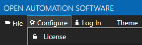
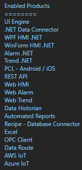
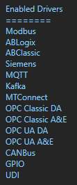
Select Configure-License and verify that MQTT is one of the available Drivers in the lower left of the form. If you do not see the MQTT driver available contact support@oasiot.com to update your license.
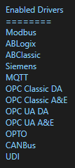
Note: You will need to be running Open Automation Software Version 8.26 or greater to support MQTT communications. You can download the latest version at www.openautomationsoftware.com/downloads/open-automation-software/
Step 3
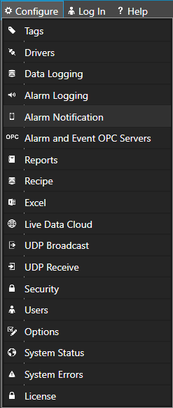
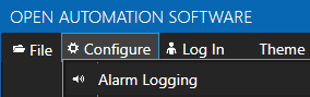
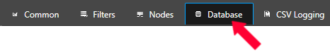
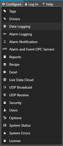
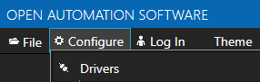
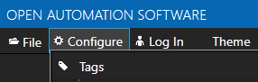
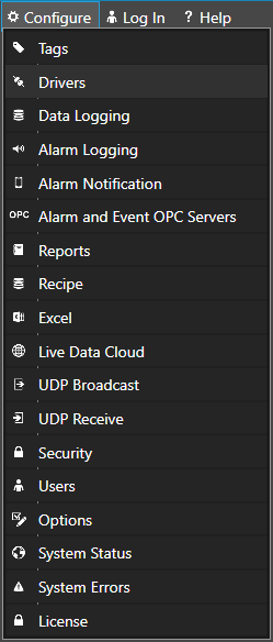
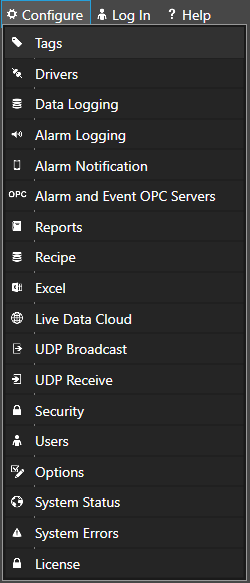
Select Configure-Drivers.
Step 4
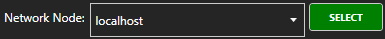
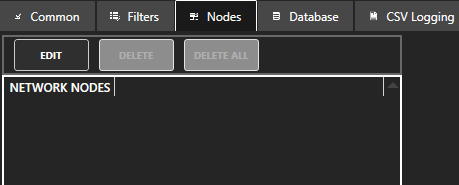
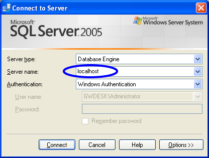
Select localhost or the remote service you wish to modify with the Select button to the right of the Network Node list.

Note: Optionally select the Live Data Cloud node if you are hosting Allen Bradley data over the Internet with a standard Internet connection.
Step 5
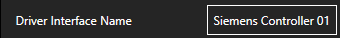
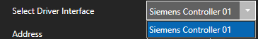
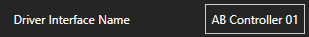
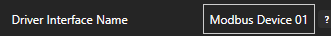
Enter a meaningful Driver Interface Name that you will refer to this physical connection when defining Tags with MQTT Source.
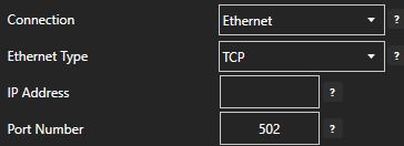
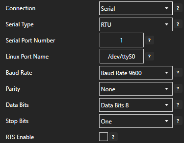
Define the properties for the desired physical connection.
Note: You may need to Set Default Network Adapter for Driver Interfaces of the operating system.
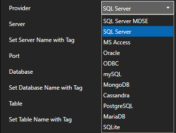
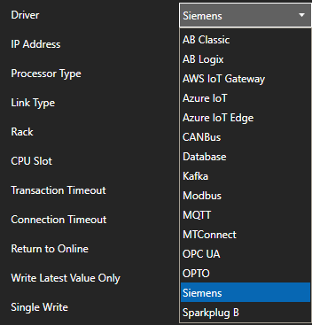
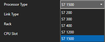
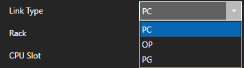
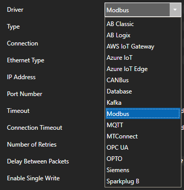
Set the driver to MQTT. Enter the IP Address of the broker. The default port is 1883.
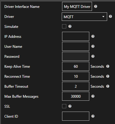
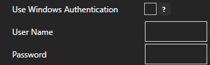
Enter the User Name and Password if required.
Keep Alive Time – Default is 60 Seconds.
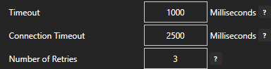
Reconnect Time – Default 10 Seconds. If the connection to the broker is lost the Reconnect Time determines how long to wait before attempting to reconnect.
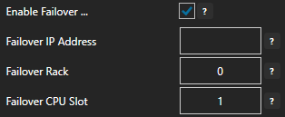
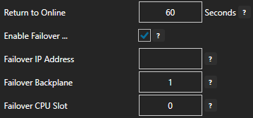
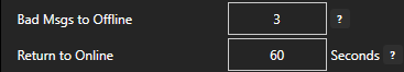
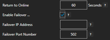
Optionally define a secondary failover MQTT Broker if the primary MQTT Broker fails with the property Enable Failover.
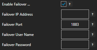
If both the primary and secondary broker are offline the Return to Online settings determines the retry frequency.
View Driver Interface Failover for more information and and video demonstrating communications failover.
Step 6
Select the Add button in the lower part of the form to add the Driver Interface as an available selection when defining Tags in the next step.

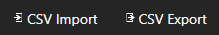
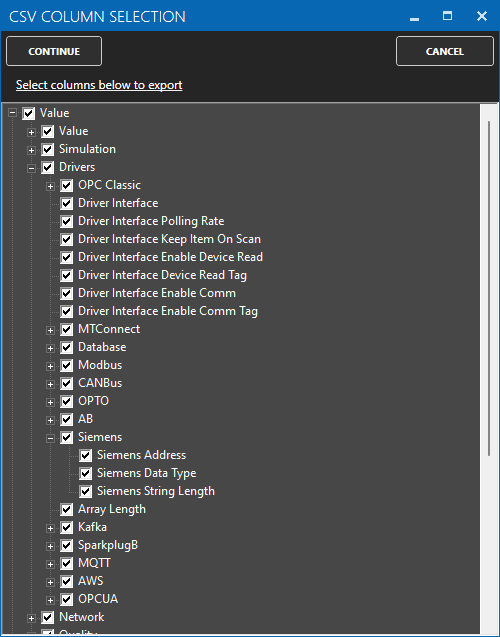
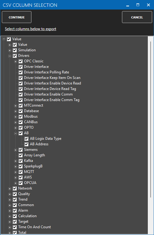
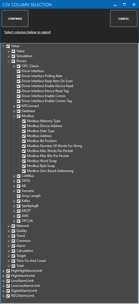
Note: If you need to define several Driver Interfaces you can use the CSV Export and CSV Import on the toolbar in the upper right together with Microsoft Excel.
Publish Selected Tags to MQTT Broker
There are 2 ways to publish data from OAS to a MQTT Broker. Both require Tags to be setup first for the data sources you want to transfer.
Note: If you wish to receive data from a MQTT Broker just to Reading Data from MQTT Broker below.
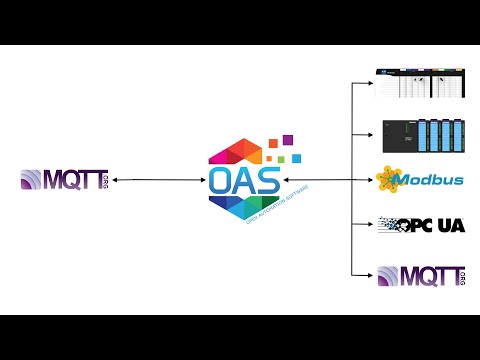
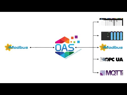
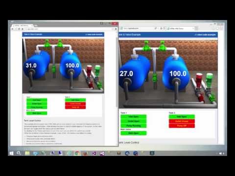
View the following video for a complete demonstration of how to publish data to MQTT Brokers, Azure IoT, and AWS IoT Gateway.
- 00:00 – Introduction
- 00:23 – Set up Tags in OAS
- 00:41 – Configure Azure IoT
- 01:53 – Publish Selected Tags
- 05:31 – Visual Studio Code
- 08:00 – Step by step instructions
- 08:12 – Bulk Publish to AWS IOT
- 09:21 – Step by step instructions / Publish Data to AWS IOT Gateway
- 09:33 – Bulk Publish to mqtt broker
- 10:29 – MQTT Explorer
- 11:20 – Step by step instructions/ Getting Started MQTT
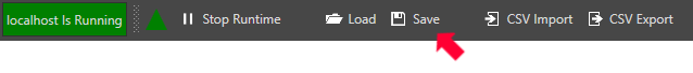
- 11:34 – Save button of the OAS Configuration tool
Step 1
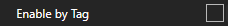
Enable Publish Selected Tags at the bottom of the Driver configuration.

Step 2
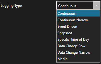
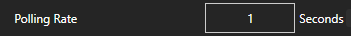
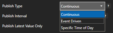
Select to publish data continuously at a specified interval, based on event, or at a specific time of day.
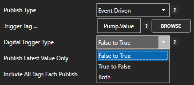
If Event Driven browse for a local or remote OAS tag that will trigger the publish. Select a Boolean tag that will change state from false to true, true to false, or both. Or choose an Integer tag that trigger a publish anytime the value changes other than 0.
Step 3
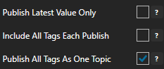
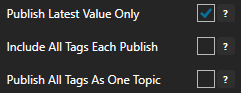
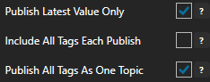
Enable Publish Latest Value Only to send only the latest value of each tag when published or disable to send all value changes since the last time a publish occurred.
Enabled Include All Tags Each Publish to send at least the latest value of each tag when published or disable to only send the tags that have changed since the last publish.
Enable Publish All Tags As One Topic to publish all tag values as one topic or disable to send each tag as its own topic.
See examples in Step 6 below for each selectable option.
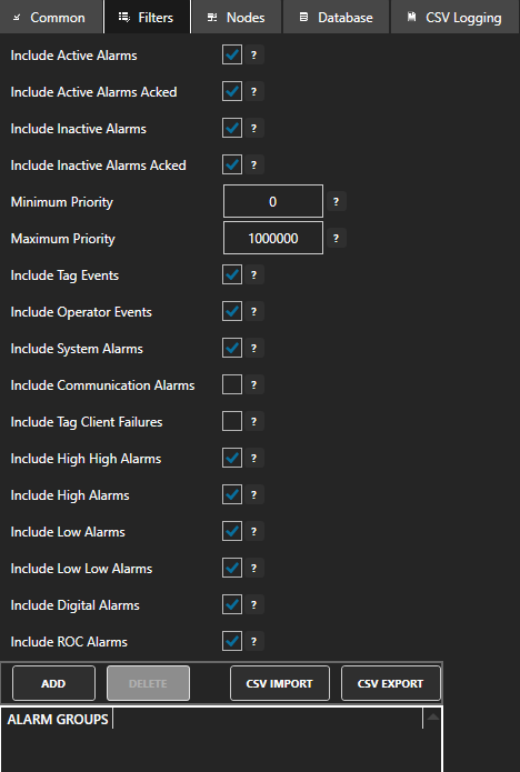
Step 4
Specify the Publish Topic Id if choosing to Publish All Tags As One Topic.
Specify the Tag Id, Value Id, an optional Quality Id, and Timestamp Id for each tag value that is sent.
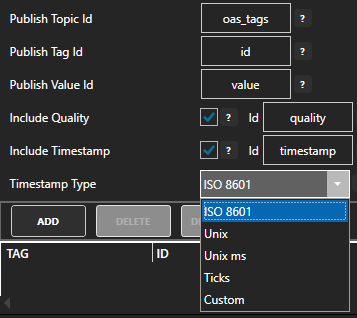
When including the Timestamp Id also specify the timestamp format, use Custom to specify your own date and time format.
Step 5
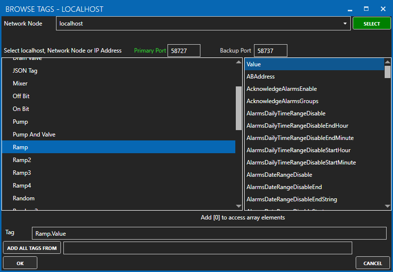
Specify local and remote OAS tag variables to include in each publish and specify the Id. Value is the current value from the data source or you can select any of the over 600 tag variables of each tag to publish.
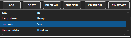
Optionally use CSV Export and CSV Import buttons to set up additional tags to publish using Microsoft Excel.
When selecting remote tags use Basic Networking syntax or Live Data Cloud syntax in the tag path.
Step 6
Select Apply Changes to begin publishing to AWS IoT Gateway. Select Save to save the new driver configuration within the tag file.
Examples:
Examples of publishing every 2 seconds with each tag value changing every second:
Topic: oas_tags
{
“id”: “Ramp”,
“value”: 39,
“quality”: true,
“timestamp”: “2022-03-21T08:55:39.000Z”
},
{
“id”: “Sine”,
“value”: 0.8090169943749475,
“quality”: true,
“timestamp”: “2022-03-21T08:55:39.000Z”
},
{
“id”: “Random”,
“value”: 10,
“quality”: true,
“timestamp”: “2022-03-21T08:55:39.000Z”
}
]
}
Topic: oas_tags
{
“id”: “Ramp”,
“value”: 16,
“quality”: true,
“timestamp”: “2022-03-21T09:03:36.000Z”
},
{
“id”: “Sine”,
“value”: 0.587785252292473,
“quality”: true,
“timestamp”: “2022-03-21T09:03:36.000Z”
},
{
“id”: “Random”,
“value”: 96,
“quality”: true,
“timestamp”: “2022-03-21T09:03:36.000Z”
},
{
“id”: “Ramp”,
“value”: 17,
“quality”: true,
“timestamp”: “2022-03-21T09:03:37.000Z”
},
{
“id”: “Sine”,
“value”: 0.6691306063588583,
“quality”: true,
“timestamp”: “2022-03-21T09:03:37.000Z”
},
{
“id”: “Random”,
“value”: 26,
“quality”: true,
“timestamp”: “2022-03-21T09:03:37.000Z”
}
]
}
Topic: Ramp
{
“value”: 35,
“quality”: true,
“timestamp”: “2022-03-21T09:07:15.000Z”
}
Topic: Sine
{
“value”: -1,
“quality”: true,
“timestamp”: “2022-03-21T09:07:15.000Z”
}
Topic: Random
{
“value”: 83,
“quality”: true,
“timestamp”: “2022-03-21T09:07:15.000Z”
}
Use Data Route to Send Data to MQTT
Step 1
See Getting Started – Data Route to define a Target tag in any source tag.
Reading Data from MQTT Broker
Step 1
Select Configure-Tags.
Select localhost or the remote service you wish to modify with the Select button to the right of the Network Node list.
Note: Optionally select the Live Data Cloud node if you are hosting Allen Bradley data over the Internet with a standard Internet connection.
Step 2
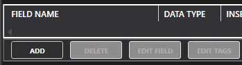
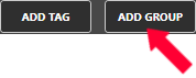
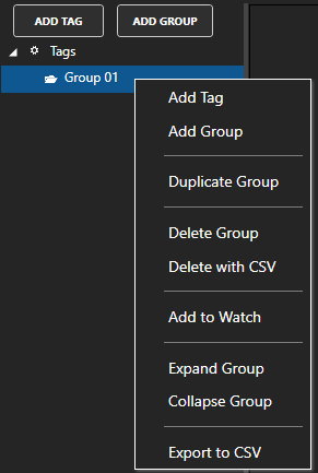
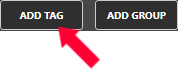
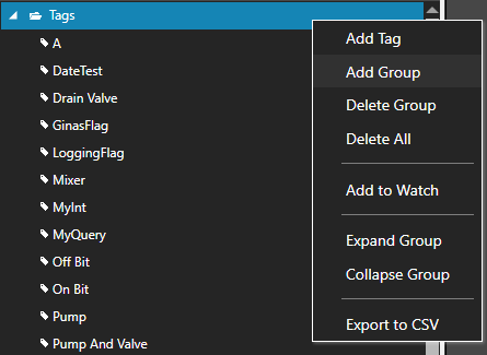
Select to Add a Tag.
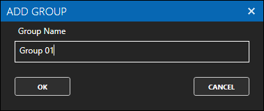
Note: You can also add organizational Groups as many levels deep as you prefer and add tags to groups. To do this first add a Group to Tags Group at the root level, then right click on the Group in the right window to add additional Groups or Tags.
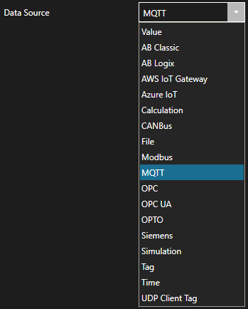
Step 3
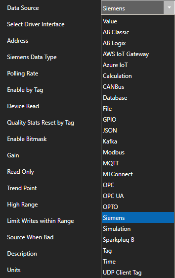
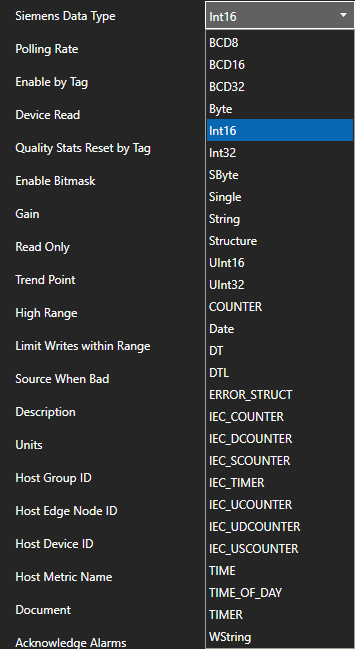
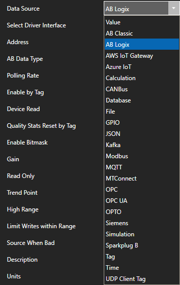
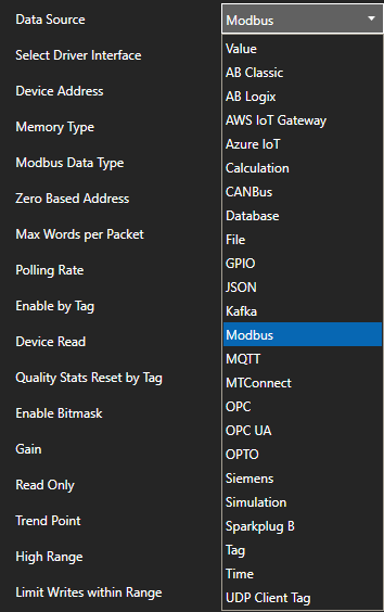
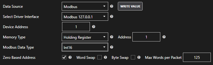
Change the Data Source Tag property to MQTT.
Step 4
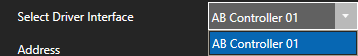
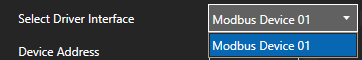
Select the correct Driver Interface from the Driver Interface pull down list.
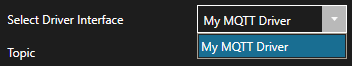
Step 5
Enter the topic.

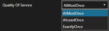
Step 6
Select the Quality of Service.
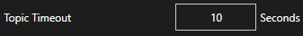
Step 7
Set the Topic Timeout – 0 = Topic will never timeout. Any number greater than 0 will cause the data to be Bad Data Quality if the broker does not publish within the time frame specified.
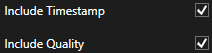
Step 8
Select to include Timestamp and or Data Quality to the topic.
This will publish to the specified topic above OAS/Items Sent/Timestamp and or OAS/ItemsSent/Quality.
Configuring the Default Network Adapter
If the communications for the MQTT driver is not working at all you may need to set the default network adapter priority in the operating system.
Step 9
To setup automated data transfer of any OAS Tag to any MQTT Broker see Getting-Started – Data Route and set the Target Destination to MQTT.
Step 10
To define multiple tags use the CSV Export and CSV Import on the toolbar in the upper right together with Microsoft Excel.
Note: You can also programmatically define Tags using the free to use OASConfig .NET Standard assembly, OPCSystems .NET Framework 4 assembly, or REST API.
Step 11
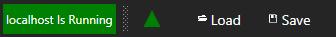
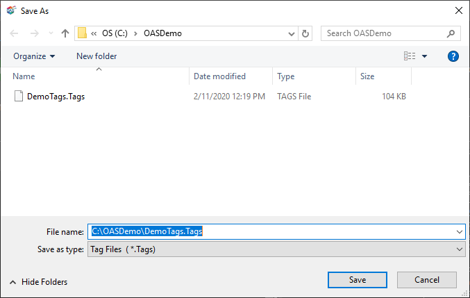
Select the Save button on the toolbar at the top.

Step 12
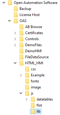
Create a directory on the local C: drive with the name OASDemo.
Save the file DemoTags.tags in the directory C:\OASDemo. Of course use the correct path for Linux.
Step 13
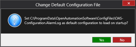
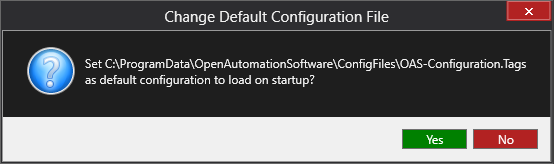
Under Configure – Options set the Default Tag Configuration File so when the computer restarts the tag file will automatically be loaded.
View Post