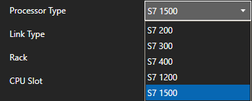
Open Automation Software Tags can be defined to connect directly to Siemens controllers with the built in Siemens Driver Interfaces which support communications over Ethernet to S7-200, S7-300, S7-400, S7-1200, and S7-1500.
Step 1 – Check Siemens License
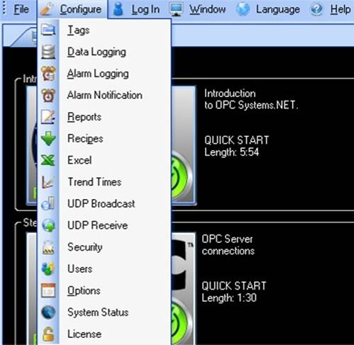
Start Configure OAS application from the program group Open Automation Software.
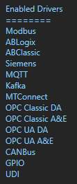
Select Configure-License and verify that Siemens is one of the available Drivers in the lower left of the form. If you do not see Siemens driver available contact support@oasiot.com to update your license.
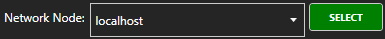
NOTE: To configure remote OAS Engines enter the IP Address or node name in the Network Node field and click on Select.
Note: You will need to be running Open Automation Software Version 8.0.0.10 or greater to support direct Siemens communications. You can download the latest version from our downloads page.
Step 2 – Configure Siemens Driver
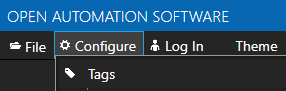
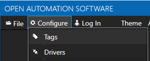
Select Configure-Drivers.
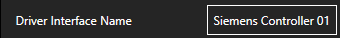
Enter a meaningful Driver Interface Name that you will refer to this physical connection when defining Tags with a Siemens Data Source.
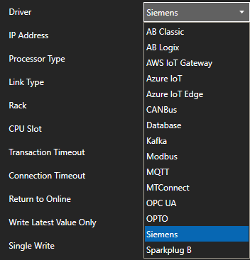
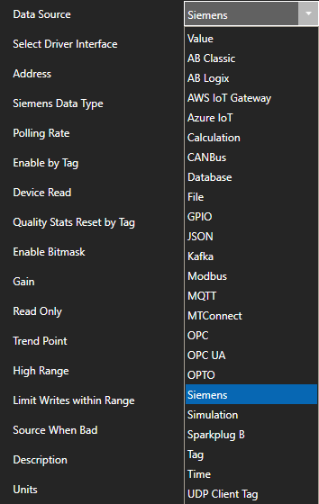
Set the Driver type to Siemens.
Define the IP Address of the controller to interface with.
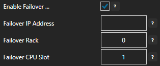
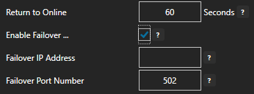
Optionally define a secondary failover of controller if the primary controller fails with the property Enable Failover.
If both the primary and secondary controllers are offline the Return to Online settings determines the retry frequency.
View Driver Interface Failover for more information and and video demonstrating communications failover.
Select the Add Driver button above the Driver list in the left pane to add the Driver Interface as an available selection when defining Tags in the next step.
NOTE: If you need to define several Driver Interfaces you can use the CSV Export and CSV Import on the toolbar in the upper right together with Microsoft Excel.
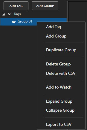
NOTE: You can add organizational Groups as many levels deep as you prefer and add tags to groups. To do this first add a Group to the root level, then right click on the Group in the right window to add additional Groups or Tags.
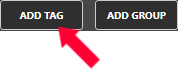
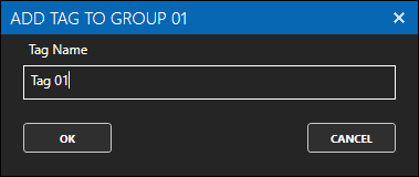
Select Add Tag to add a tag to the group selected.
Change the Data Source Tag property to Siemens.
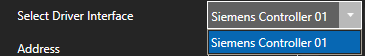
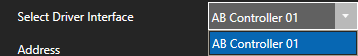
Select the correct Driver Interface from the Driver Interface pull down list.
Example: DB1.DBD1 would be used to access a single float variable from data block 1.
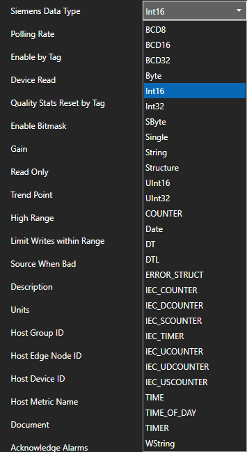
Select the correct Siemens Data Type.
Specify the desired Polling Rate for the Tag.
To disable communications to the device you can use Enable by Tag to control when communications is active. Leave this property disabled to establish communications at all times.
The Device Read property can be used to disable continuous polling and request data on event from the transition from false to true of a value of a Boolean tag. Leave this property disabled to establish communications at all times.
Select Apply Changes to make the changes active on the tag.
Check that the data quality of the tag is Good Quality and the value from the device is returned.
Note: If error code 0x00000005 – Address does not exist or is out of range is returned as a System Error uncheck Optimized block access attribute of dbOptimized in the controller program and re-compile and upload to the controller.
To define multiple tags use the CSV Export and CSV Import on the toolbar together with Microsoft Excel.
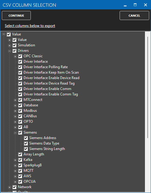
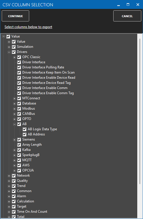
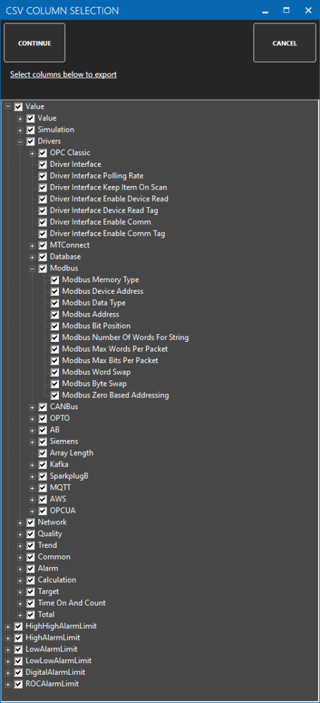
When exporting tags choose which columns to include in the CSV file. There are over 800 properties available for use in each tag and reducing the amount of data can help to focus on the properties of interest.
Tags can be automatically setup by using the One Click Allen Bradley feature that reads all variables from an online controller or controller file and creates tags based on the variables and data types found. The One Click feature is available both online and offline. We recommend using the online method. Instructions for the online method are below as well as a video. There is a video at the bottom of the page for the offline method.
Online One Click Allen Bradley
Import Allen Bradley variables from a controller to Open Automation Software.
Step 1
Open the OAS Configure application from the program group Open Automation Software in your Start Menu.
Step 2
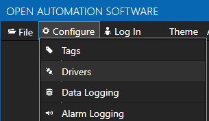
Select Configure Drivers from the top Menu.
Step 3
Select localhost or the remote service you wish to modify with the Select button to the right of the Network Node list.
Step 4
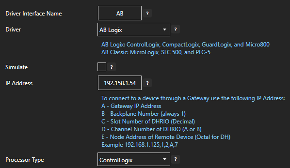
Enter a friendly name in the Driver Interface Name box. In the Driver drop down list, select AB Logix. Enter the IP address for your device in the IP Address box.
Step 5
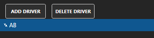
Click the Add Driver button in the pane on the left. Your new driver will appear in the list under it.
Step 6
Select Configure Tags from the top Menu. Select your Network Node.
Step 7
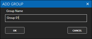
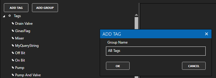
Right Click on the the Tags group at the top of the tag browser on the left and choose Add Group. In the Group Name box that opens, enter AB Tags. Say OK.
Step 8
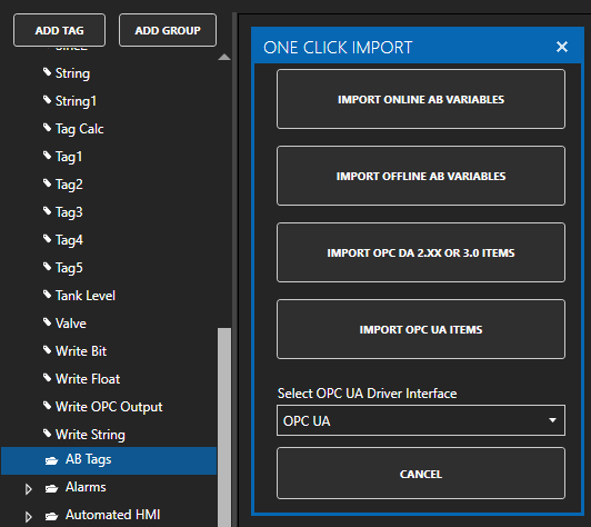
Select your new AB tag group from the tree. Click One Click Import from the top menu bar. In the One Click Import box that opens, choose Import Online Ab Variables.
Step 9
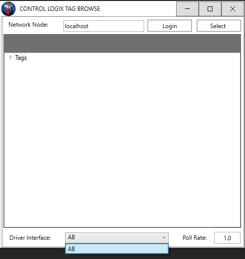
In the Control Logix Tag Browse window that opens, Select your Network Node and then select your AB Driver Interface from the drop down list.
Step 10
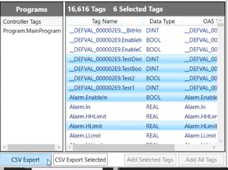
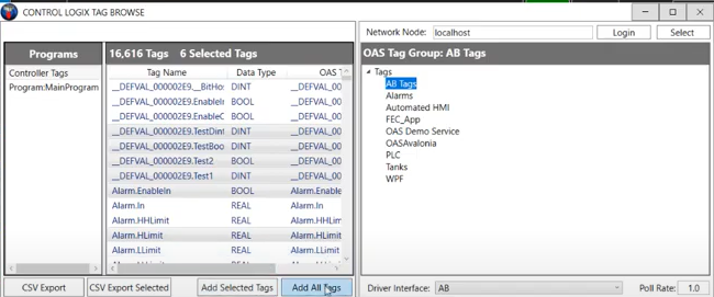
Select the program you want to import from under the Programs list that appears. A list of all the tags in the PLC will appear. You can select individual tags, groups of tag or all of the tags from the list.
Step 11
Select the AB Tags group from the Tags window on the right. Specify a Poll Rate if desired. Choose Add Selected Tags or Add All Tags.
Note: You can use the CSV Export or CSV Export Selected buttons at this point to export your tags into a CSV file to be used later to import into OAS.
Step 12
Once you have received the success message, you can close the Online Import window. Refresh your tag browser by re-selecting your network node. Your new tags should now appear under the AB folder you created.
Offline One Click Allen Bradley
Import Allen Bradley variables from a program file to Open Automation Software.
There is also a custom data type editor to add or remove variables that will be added to the file abdt1.xml in the directory C:\Program Files\Open Automation Software\OAS. If you make changes to this file make sure to backup abdt1.xml before you perform any software update.
Open Automation Software Tags can be defined to connect directly to Allen Bradley controllers with the built in AB Logix and AB Classic Driver Interfaces which support communications over Ethernet to ControlLogix, CompactLogix, GuardLogix, and Micro800 with the AB Logix driver, and MicroLogix, SLC 500, and PLC-5 with the AB Classic driver. The following steps can be used to setup direct communications with Allen Bradley controllers.
Step 1 – Check Allen Bradley License
Start Configure OAS application from the program group Open Automation Software.
Select Configure-License and verify that ABLogix and / or ABClassic is one of the available Drivers in the lower left of the form. If you do not see either AB drivers available email support@oasiot.com to update your license.
NOTE: To configure remote OAS Engines enter the IP Address or node name in the Network Node field and click on Select.
ABLogix is needed for ControlLogix, CompactLogix, GuardLogix, and Micro800.
ABClassic is needed for MicroLogix, SLC 500, and PLC-5.
Enter a meaningful Driver Interface Name that you will refer to this physical connection when defining Tags with an AB Data Source.
Set the Driver type to AB Logix or AB Classic.
AB Logix: ControlLogix, CompactLogix, GuardLogix, and Micro800 AB Classic: MicroLogix, SLC 500, and PLC-5
Define the IP Address of the controller to interface with.
To connect to a device through a Gateway use the following IP Address: A – Gateway IP Address B – Backplane Number (always 1) C – Slot Number of DHRIO (Decimal) D – Channel Number of DHRIO (A or B) E – Node Address of Remote Device (Octal for DH) Example 192.168.1.125,1,2,A,7
AB Logix:
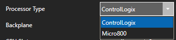
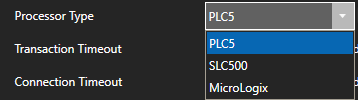
Set the Processor Type.
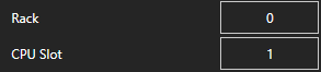
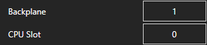
Set the Backplane and CPU Slot number if using ControlLogix.
AB Classic:
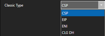
Select the AB Classic Type.
CSP: Default for PLC5 and SLC5/05 Direct Connections EIP: Used for Micrologix 1100 and newer PLC5 and SLC5/05 Direct Connections ENI: 1761-NET-ENI connections to PLC5, SLC500 and MicroLogix CLG DH: Used for ControlLogix Gateway to PLC5, SLC500, MicroLogix. and ControlLogix Gatway to PLC5 and SLC5/04 via DH+
Set the Processor Type.
NOTE: To increase the processor overall speed in response in the logix 5000 program right click on the processor in the tree and select properties. In the Advanced Tag you can adjust System Overhead Time Slice. Increasing this value will increase the communications throughput. The Default is 20%:
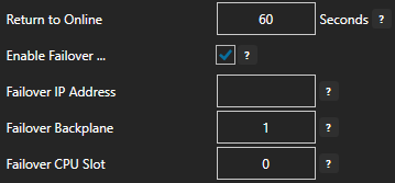
Optionally define a secondary failover of controller if the primary controller fails with the property Enable Failover.
If both the primary and secondary controllers are offline the Return to Online settings determines the retry frequency.
View Driver Interface Failover for more information and and video demonstrating communications failover.
Select the Add Driver button to add the Driver Interface as an available selection when defining Tags in the next step.
NOTE: If you need to define several Driver Interfaces you can use the CSV Export and CSV Import on the toolbar in the upper right together with Microsoft Excel.
Step 3 – Configure Allen Bradley Tags
Select Configure-Tags.
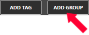
Select Add Group to add a group to place tags in.
NOTE: You can add organizational Groups as many levels deep as you prefer and add tags to groups. To do this first add a Group to the root level, then right click on the Group in the right window to add additional Groups or Tags.
Select Add Tag to add a tag to the group selected.
Change the Data Source Tag property to AB Logix or AB Classic.
Select the correct Driver Interface from the Driver Interface pull down list.
If using AB Logix select BROWSE to browse for the Address in the controller.
NOTE: Controllers for AB Classic do not support browsing, manually set the Address.
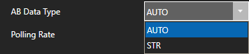
If communicating to a string variable set the AB Data Type to STR, use AUTO for all other data types.
Set the desired Polling Rate for reading from the device. The rate can be set to 100 nanoseconds, but the lowest practical rate would be 20 milliseconds or 0.02 seconds.
To disable communications to the device you can use Enable by Tag to control when communications is active. Leave this property disabled to establish communications at all times.
The Device Read property can be used to disable continuous polling and request data on event from the transition from false to true of a value of a Boolean tag. Leave this property disabled to establish communications at all times.
Select Apply Changes and verify the Value and data quality is good.
Check that the data quality of the tag is Good Quality and the value from the controller is returned.
Note: You may want to use One Click Allen Bradley to add tags from the controller automatically.
How to automatically import Allen Bradley variables to Open Automation Software.
Another way to define multiple tags is to use the CSV Export and CSV Import on the toolbar together with Microsoft Excel.
When exporting tags choose which columns to include in the CSV file. There are over 800 properties available for use in each tag and reducing the amount of data can help to focus on the properties of interest.
Open Automation Software Tags can be defined to connect directly to Modbus slave devices or host data to Modbus masters with the built in Modbus Driver Interface which supports communications over Ethernet and Serial interfaces for Modbus TCP, Modbus RTU, and Modbus ASCII protocols.
You can view the Getting Started with Modbus Video to familiarize yourself with the following steps to setup Modbus communications.
00:00 – Introduction
00:30 – Configure OAS Application
02:26 – How to Configure Tags
03:00 – Data Type
04:33 – Address for memory location
04:49 – Modbus Data Type
05:26 – Simulator Communication
06:30 – Data Route Functionality
07:43 – Tag Management
07:46 – CSV Export
08:35 – Set Up Tags Programmatically
08:56 – Data Destinations
09:22 – Save Tag Configuration
09:54 – Further Questions
The following steps can be used to setup direct communications with Modbus devices.
Step 1 – Check Modbus License
Start Configure OAS application from the program group Open Automation Software.
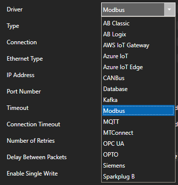
Select Configure-License and verify that Modbus is one of the available Drivers in the lower left of the form. If you do not see Modbus available contact support@oasiot.com to update your license.
NOTE: To configure remote OAS Engines enter the IP Address or node name in the Network Node field and click on Select.
Enter a meaningful Driver Interface Name that you will refer to this physical connection when defining Tags with a Modbus Data Source.
Set the Driver type to Modbus.
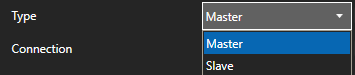
Set the Type as Master to communicate with a Modbus device. Set to Slave if OAS is to interface with one or more Modbus masters.
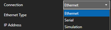
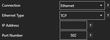
Set the Connection type as Ethernet or Serial.
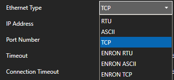
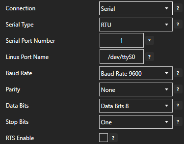
Set the Ethernet Type or Serial Type to the Modbus protocol to use. For Ethernet connections TCP is the most common. For Serial connections the most common would be RTU or ASCII. OAS supports all protocols on both connection types.
Ethernet Connection:
Specify the IP Address and Port Number. For Master connections specify the IP Address of the Modbus device. For Slave connections et the IP Address to the computer IPv4 IP address or network node name if the master is on a remote PC. You can also use 127.0.0.1 or localhost if the Modbus master will be on the same computer as OAS.
Serial Connection:
Specify the Serial Port Number for Windows or Linux Port Name for Linux.
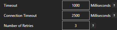
Specify Timeout and Number of Retries when a communication failure occurs.
For Master connections Enable Single Write controls how individual writes are performed.
When enabled Function Code 05 to be used when there is only one Output Coil to write, Function Code 06 to be used when there is only one Holding Register to write. When disabled Function Code 15 will always be used for Output Coils and Function Code 16 for Holding Registers.
For Master connections Enable Multiple Write allows multiple holding registers with contiguous addresses to be sent in one packet.
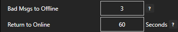
Set Bad Msgs to Offline to the number of successive communication failures to stop communications to the device and retry at the rate specified in Return to Online.
NOTE: Set Bad Msgs to Offline to 0 to leave the device online at all times.
For redundancy support optionally define a secondary failover device if the primary device fails with the property Enable Failover.
If both the primary and secondary device are offline the Return to Online settings determines the retry frequency.
View Driver Interface Failover for more information and and video demonstrating communications failover.
The Comm Bad and Comm Good properties can be used to assign an Integer Tag to be updated with the communication summary of the driver interface.
Comm Bad Count
Will set a tag with the driver interface Comm Bad Count. The number of times the communications of the driver interface has transitioned from good to bad. Can be reset to 0 when tag defined to Comm Count Reset transition from false to true.
Comm Bad Read Count
Will set a tag with the driver interface Comm Bad Read Count. The number of communication reads from the device has failed for the driver interface. Can be reset to 0 when tag defined to Comm Count Reset transition from false to true.
Comm Bad Time
Will set a tag with the driver interface Comm Bad Time. The time in seconds the communications to the device has been bad. Can be reset to 0 when tag defined to Comm Count Reset transition from false to true.
Comm Bad Write Count
Will set a tag with the driver interface Comm Bad Write Count. The number of write failures to the device. Can be reset to 0 when tag defined to Comm Count Reset transition from false to true.
Comm Good Count
Will set a tag with the driver interface Comm Good Count. The number of times the communications of the driver interface has transitioned from bad to good. Can be reset to 0 when tag defined to Comm Count Reset transition from false to true.
Comm Good Read Count
Will set a tag with the driver interface Comm Good Read Count. The number of communication reads from the device has succeeded for the driver interface. Can be reset to 0 when tag defined to Comm Count Reset transition from false to true.
Comm Good Time
Will set a tag with the driver interface Comm Good Time. The time in seconds the communications to the device has been Good. Can be reset to 0 when tag defined to Comm Count Reset transition from false to true.
Comm Good Write Count
Will set a tag with the driver interface Comm Good Write Count. The number of successful writes to the device. Can be reset to 0 when tag defined to Comm Count Reset transition from false to true.
Comm Count Reset
Define a Boolean tag that can reset the Comm Counts and Times. A transition from false to true will reset the counts.
Select the Add Driver button in the upper left to add the Driver Interface as an available selection when defining Tags in the next step.
Note: If you need to define several Driver Interfaces you can use the CSV Export and CSV Import on the toolbar with Microsoft Excel.
NOTE: You can add organizational Groups as many levels deep as you prefer and add tags to groups. To do this first add a Group to the root level, then right click on the Group in the right window to add additional Groups or Tags.
Select Add Tag to add a tag to the group selected.
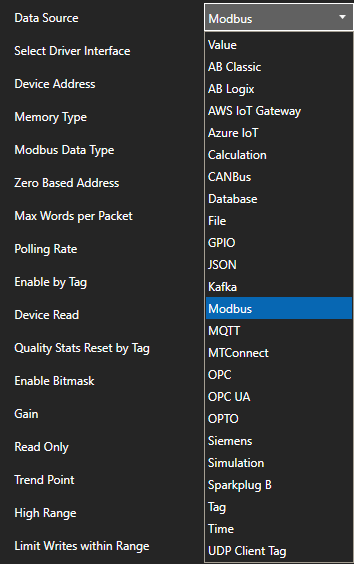
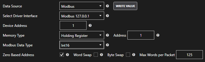
Change the Data Source Tag property to Modbus.
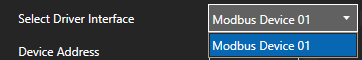
Select the correct Driver Interface from the Driver Interface pull down list.
Specify the Device Address (set as -1 if it is not to be used on Ethernet)
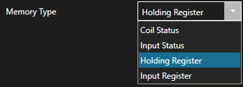
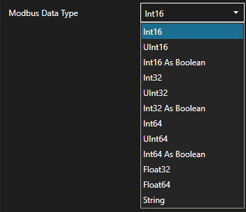
Select the correct Memory Type from the Memory Type pull down.
NOTE: Use the “As Boolean” types to access bits of a 16, 32, or 64 bit Integer.
Specify the Address for the memory location.
The base of the memory type will be added to the Address.
Extended addressing is also supported.
To communicate to 410001 set the Memory Type to Holding Register and the address to 10001.
To communicate to 465535 set the address to 65535.
Following are some examples.
To access 40,001 use address of 1
To access 49,999 use address of 9,999
To access 50,000 use address of 10,000
To access 410,001 use address of 10,001
To access 420,000 use address of 20,000
To access 430,000 use address of 30,000
To access 440,000 use address of 40,000
To access 450,000 use address of 50,000
To access 460,000 use address of 60,000
To access 465,535 use address of 65,535
NOTE: Zero Based Addressing will subtract 1 from the address when communicating to the device.
Example: Communicating to Holding Register 40000 the Memory Type will be Holding Register and the Address would be 1.
For Input Register and Holding Register Memory Types select the correct Modbus Data Type.
Word Swap and Byte Swap can be enabled to swap words or bytes within the value received or sent.
Max Words per Packet is used to control the maximum number of words allowed in each communication packet. OAS can support up to 10,000 words per packet if the device can support it. Most Modbus devices only support 125 words per packet.
Set the desired Polling Rate for reading from the device. The rate can be set to 100 nanoseconds, but the lowest practical rate would be 20 milliseconds or 0.02 seconds.
To disable communications to the device you can use Enable by Tag to control when communications is active. Leave this property disabled to establish communications at all times.
The Device Read property can be used to disable continuous polling and request data on event from the transition from false to true of a value of a Boolean tag. Leave this property disabled to establish communications at all times.
Each Modbus Tag provides communication stats for success or failure on reading and writing to a device. Use the property Quality Stats Reset by Tag to define a Boolean tag that will reset the stats on a value transition from false to true.
Select Apply Changes to make the changes active on the tag.
Check that the data quality of the tag is Good Quality and the value from the device is returned.
To define multiple tags use the CSV Export and CSV Import on the toolbar together with Microsoft Excel.
When exporting tags choose which columns to include in the CSV file. There are over 800 properties available for use in each tag and reducing the amount of data can help to focus on the properties of interest.
Tags can be automatically setup by using the One Click OPC feature that browses OPC Servers automatically and creates tags based on the OPC Items defined in the OPC Server. You can then delete tags from the configuration that you do not want.
View the following 2 minute video on how to use the One Click OPC Feature or follow the steps in the table below.
Step 1
Start Configure OAS application from the program group Open Automation Software.
Select Configure-Tags.
NOTE: To configure remote OAS Engines enter the IP Address or node name in the Network Node field and click on Select.
Select Add Group to add a group to place tags in.
To begin the One Click OPC process select the Group you would like to import to in the Tag configuration. If you want to import to the Root Level, select the Tags Group at the top of the tree.
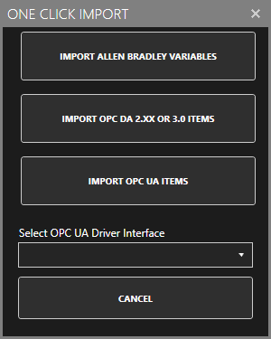
Then select the One Click Import button on the top menu bar.
Click on the Import OPC DA 2.XX or 3.0 Items Button in the pop up window.
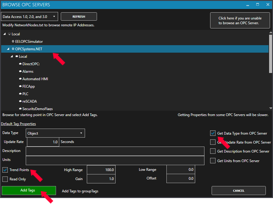
Use the One Click OPC Wizard to browse for a branch as a starting position within an OPC Server or just select the OPC Server name itself to add all items from the selected OPC Server. For the best networking design select OPC Servers from Local even if you are configuring a remote OAS Service.
Select to enable the options to Get Data Type from OPC Server and optionally the Descriptions. Additionally if you want to specify to Trend all of the points select Trend Points.
Click Add Tags and it will automatically add all of the OPC Items from the OPC Server Branch you have selected and all sub Branches beneath it.
Step 2
Select the Save button on the toolbar at the top.
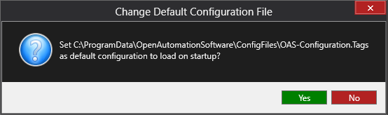
Enter a file name to be saved in C:\ProgramData\OpenAutomationSoftware\ConfigFiles directory on Windows or ConfigFiles subdirectory on Linux.
When prompted to set the file as the default configuration to load on startup select Yes.
In the OAS platform, a Tag is the fundamental representation of a unit of data. At the most basic level, a Tag consists of a TagName, a Value, a Timestamp and a Quality.
The TagName parameter stores the name of the tag, including the Tag Group (see the Tag Groups section).
The Value parameter holds the last known state – we’ll look at data types and sources shortly.
The Timestamp parameter holds the timestamp of when the Tag’s value parameter was last updated.
Finally, the Quality parameter tells us whether the last known value is available and valid. The quality parameter is important when dealing with issues like incompatible data types, unreliable network connections and invalid values. When such issues are detected and the quality is “bad” we can use different strategies to deal with such issues. For example, we could do nothing, or we could tell OAS to hold the last known value and hide the fact that the quality is bad, or we could fall back to a default value.
Tag Parameters
It is important to understand that a Tag is actually a structure consisting of hundreds of parameters relating to the unit of data being measured and the enabled features. We’ve just introduced four of those parameters, but there are literally hundreds of parameters that can be accessed for each tag. Tag parameters can be grouped into roughly the following categories:
Configuration
Data (such as Value, Timetsamp and Quality)
Counters
Alarms
DigitalAlarm
HighAlarm
HighHighAlarm
LowAlarm
LowLowAlarm
ROCAlarm
Some of the parameters are specific to certain features available in your license. For example, alarm parameters will not be used if you do not have any of the alarm features enabled in your license.
👉 For a full listing of tag parameters see: Tag Variables 🔗
Tag Groups
You can use Tag Groups to help organize your Tags into a hierarchical structure. You can think of Tag Groups like files and folders in your operating system, where the folders are the Tag Groups and the files are your Tags. This allows you to organize your Tags in a way that models your physical assets, devices and sensors. For example, you could group your Tags by site or location and then further group them by devices, sensors or function. It is really up to you how you want to model your data.
In a file system structure you would use file paths to refer to individual files – for example /home/user/my_file. OAS uses a similar approach – to reference a Tag you will use what is called a tag path. Below are some examples of tag paths based on the above diagram:
MyTag6.Value
TagGroup1.MyTag2.Value
TagGroup2.NestedTagGroup.MyTag3.Value
You can see that in the last part of the tag path we used the keyword Value. This is because simply referring to a tag path without a parameter at the end is not a valid tag path. A full tag path must contain the tag groups (if any), the tag name and the parameter that you wish to read/write.
Data Type
The Value parameter of a Tag is what holds the state of the unit of data that the Tag represents – this could be a measurements from a sensor, the state of a switch, a calculation or some other custom data points. How do we know what kind of data is supposed to be stored in the Tag value? How do we know it’s valid? To allow OAS to determine this, each Tag must also have a Data Type. Just like variables have a Type in most programming languages, Tags must also be configured with the correct data type.
Specifying the data type has two important functions – to validate the Tag value and to automatically convert values where possible. By setting the data type of a Tag you are telling OAS what your expectations are of what kinds of data are allowed to be stored in the Tag value. For example, a Boolean data type expects values to be True or False. However, what if the source is an integer? This is where the data type also provides data type conversion if required. For example, if the data type is Boolean and an integer value is written to the Tag, OAS will convert a zero (0) value to False and any non-zero value to True. It will do this automatically and the quality of the Tag will remain in a Good Quality state.
However, in other cases, if OAS can’t automatically convert a value, because it does not match the correct type, then OAS will set the quality of the Tag to Bad Quality. This is important because it allows you to take appropriate action (such as using the Source When Bad parameter to handle this case) or logic in your own custom application. For example, trying to write a floating point number to a Boolean type is not valid.
There are a number of supported data types in OAS including Boolean, Integral, Floating-point, Array, String, JSON and Object types. The following diagrams provides a visual summary of the data types.
Data Source
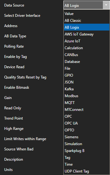
The most fundamental and powerful feature of the OAS Platform is the ability to source data from a wide range of data sources and make configuration very simple. Some data sources require you to first configure a driver before you can set the data types, whilst other data sources are built-in to the core OAS functionality, such as source data from another tag, creating calculations or creating a simulation.
Each Tag must have a data source configured using the Tag’s DataSource parameter. By default, this parameter is set to the Value data source. This is a standard internal data source that simply means: whatever value you manually write into my Value parameter will be my data source. As long as it does not fail validation based on the defined Data Type, the Tag’s quality will always be Good Quality. When a Tag’s data source is set to the Value data source the Tag will act like a variable that can be updated through any of the OAS clients or API calls.
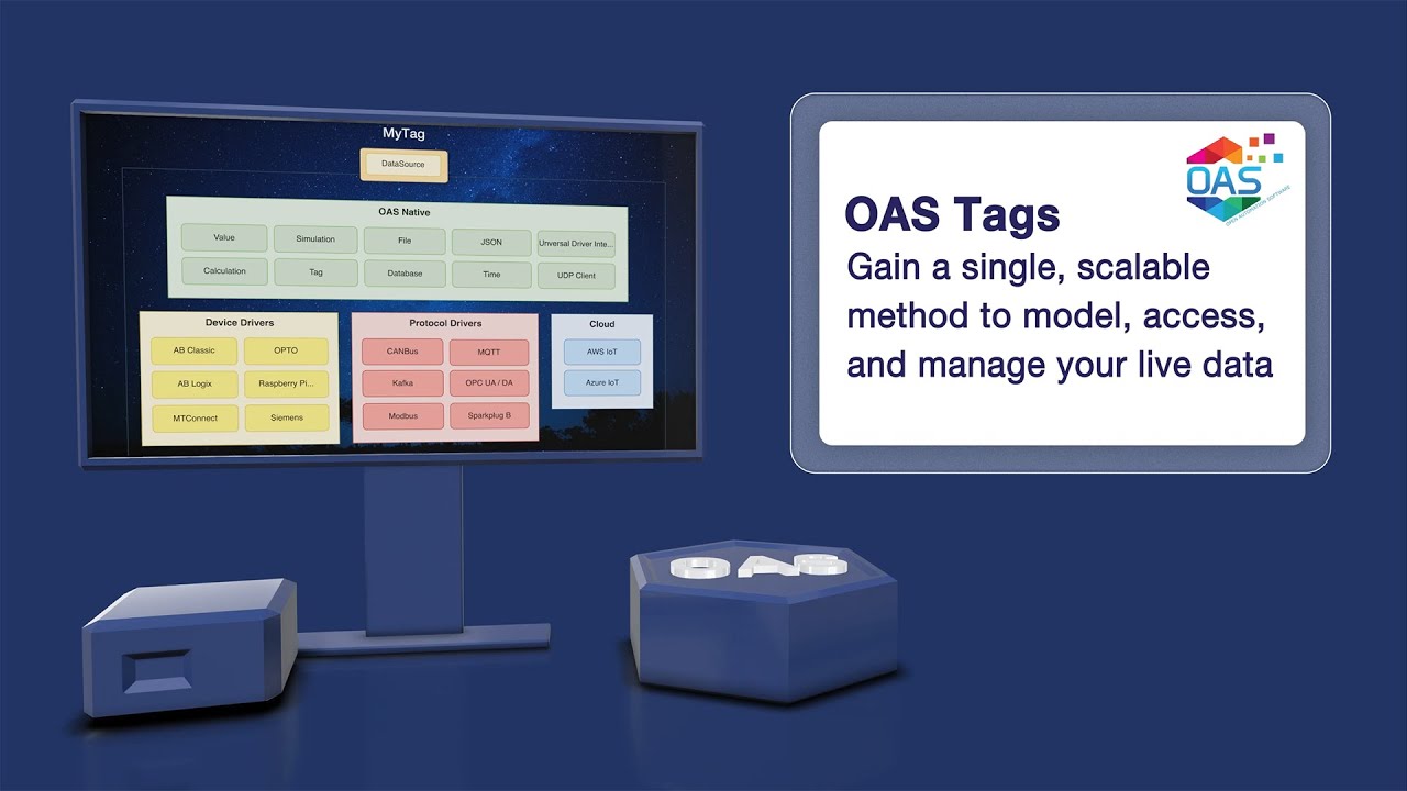
The following diagram shows the available data types grouped into high level categories including OAS native data source types, drivers, protocols and cloud integrations.
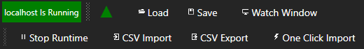
The Service must be in Runtime mode in order to process values for trending, alarming, data logging, recipe execution, report generation, data transfer, and communications. You can Start and Stop Runtime from any of the Service configuration windows.
To Start Runtime select the Start Runtime Button in any Service modification window of the OAS Configuration application or from the OAS Service Control application.
To Stop Runtime select the Stop Runtime Button in any Service modification window of the OAS Configuration application or from the OAS Service Control application.
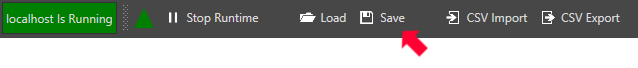
You can make add, delete or make modifications to all configurations while the Service is in Runtime mode. Tag configurations files can only be loaded when not in Runtime, but Tag configuration files can be saved during Runtime. All other modifications can be done while in Runtime if desired.
Make certain to save the modifications if you desire the changes to be retentive for the next time the Service is started.
If one or more Live Data Cloud services are subscribed to the service you are connecting to the Live Data Cloud list will populate with all of the remote Live Data Cloud services that are available to connect to. Use the Select button to the right of the Live Data Cloud list to connect to the Live Data Cloud service for remote configuration.
See Live Data Cloud for more information on how to setup Remote SCADA Hosting to host a remote data source through a standard Internet connection.
When accessing any of the configurations you will select the desired network node to modify. Enter the IP Address, Network Node Name, or Registered Domain Name in the Network Node field and click the Select. This allows you to modify configurations on remote systems.
Use the pull down to select previously selected services. Use the EDIT button to add additional network nodes to the pull-down list.
If other Live Data Cloud nodes are hosted through selected network node the Live Data Cloud list will populate in the Live Data Cloud pull-down.
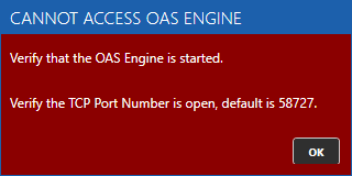
If the OAS Engine is not running on the system or the TCP Port is blocked you will see a warning dialog to start the service.
If successfully connected to the OAS Engine the status of the service will appear at the top along with configuration buttons to load, save, and modify a configuration.