Troubleshoot Bad Data
How to identify and resolve communications errors with data sources.
- 0:00 - Introduction
- 0:40 - Bad Tags
- 3:30 - System Errors
- 4:20 - Watch Window
- 6:20 - Error Logging
- 7:20 - Troubleshooting Guides
- 8:55 - Contact Us
How to identify and resolve communications errors with data sources.
How to identify and resolve communications errors with data sources.
How to identify and resolve communications errors with data sources.
Below are some helpful troubleshooting steps to resolve bad data quality for tags with a Data Source of Modbus.
![]()
To communicate to Modbus slave devices set the Type under Configure-Drivers to Master so OAS is a Modbus Master.
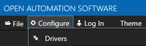
When the Type is set to Slave OAS can act as a Modbus slave for Modbus masters to read and write data from OAS.
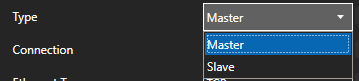
The protocol type can be set to TCP, RTU, or ASCII. Although OAS can support all 3 protocols on either Ethernet or Serial interfaces it is typical to use TCP over Ethernet and RTU or ASCII over Serial.
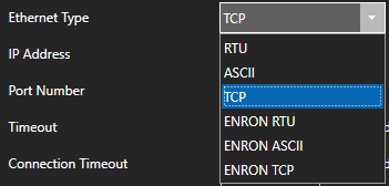
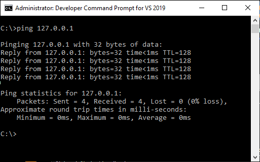
When connecting to a Modbus slave over Ethernet the device will need to be reachable from the OAS system. Use Windows Command Prompt or Linux terminal where the OAS Engine is running to ping the device to verify it is reachable.
Specify the correct Memory Type for the data within the device.
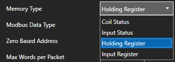
The Address field should not contain the base address of the memory type used.
![]()
For example to access holding register 40,001 set the Memory Type to Holding Register and the Address to 1.
Extended addressing is also supported. To communicate to 410001 set the Memory Type to Holding Register and the address to 10001.
Holding Register Address Range
Zero Based Addressing will subtract 1 from the address when communicating to the device.
![]()
Example: When communicating to Holding Register 40000 the Memory Type will be Holding Register and the Address would be 1.
Refer to the vendor's documentation if the device uses 0 base addressing or 1 base addressing.
The Modbus Data Type for the tag should be set to the correct type based on the data to obtained from the controller.
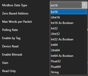
To access 4 byte single floats use Float32. To access 8 byte double floats use Float64.
To access individual bits of a Holding Register or Input Register use Int16 As Boolean, Int32 As Boolean, or Int64 As Boolean.
Also match the OAS tag Data Type to the correct value type to be set. If you are unsure of the data type use Object to see the result.
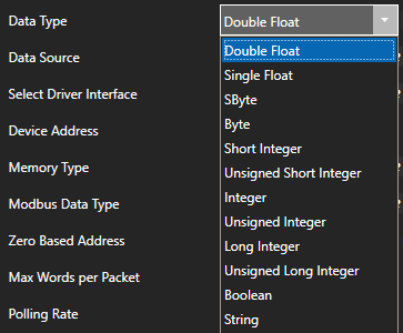
Note: If you are using Gain and Offset in a tag to scale an integer value to a floating point value use Double Float or Single Float as the Data Type.
If one or more of the Tags defined to the Driver Interface has invalid address defined or the address does not exist in the device the remaining good addresses can be affected with either taking the device offline or invalid packet request or response.
To isolate one or more tags to their own dedicated communication channel select the existing driver interface and change the name to a new unique name and select Add Driver.
![]()
To define a tag to the new driver select Configure-Tags, then select the tag you want to isolate to select the new driver interface.
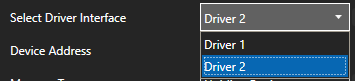
Select Apply Changes.
![]()
If the data quality changes to good for the tag then resolve the other addresses in the tags defined to the first driver interface used.
![]()
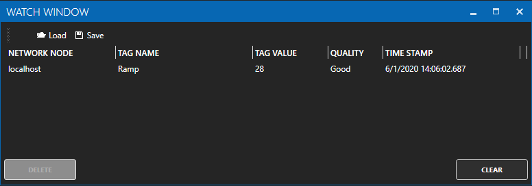
To help you further identify which tag addresses are bad use the Tag Watch Window to view multiple tags in one window.
To add a tag to the Watch Window, select any tag or tag group and right click on it. Then choose Add to Watch from the context menu.
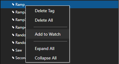
The tag you selected will then appear in the Watch Window.
Set Bad Msgs to Offline to 0 temporarily so the Driver Interface will remain online to continue to poll all addresses.
![]()
If an address is defined that does not exist in the device other tags with valid addresses can also be affected if the address is within range of the Max Words per Packet.
You can temporarily override packet optimization by adjusting the Max Words per Packet to 1 to poll each address independently in its own packet request. See Max Words per Packet following. Use Tag CSV Export and Import to set multiple tags with the same Max Words per Packet.
Once you identify which addresses are invalid investigate if the address exists in the device or refer to the vendor's documentation to find the correct addresses to use.
Some Modbus devices have a limitation of packet size. Refer to the vendor's documentation as to what maximum packet size it can support. There are 2 bytes to each word, so if the device can support 250 bytes, the Max Words per Packet can be left at the default of 125.
![]()
The default value of Max Words per Packet is 125.
Note: Setting Max Words per Packet to a lower value can decrease the overall communication speed to the device. Use the highest possible the device supports for the best performance.
Refer to the device vendor's documentation to determine if bytes or words need to be swapped to covert the raw integer values received and sent. If so use the properties Word Swap and / or Byte Swap.
![]()
When the property Device Read is enabled polling communications will be disabled and read requests will only be performed when the tag defined for the Device Read transitions from false to true. If data is to be polled continuously from the device disable the tag property Device Read.
![]()
The Enable by Tag property is used to define a Boolean tag that will enable or disable communications for the tag. If data is to be polled continuously from the device disable the tag property Enable by Tag.
![]()
Use Configure-License to verify that the Driver Modbus is enabled.
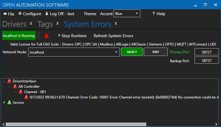
Select Configure-System Errors and expand any Modbus or Driver Interface error to see the details of the error.
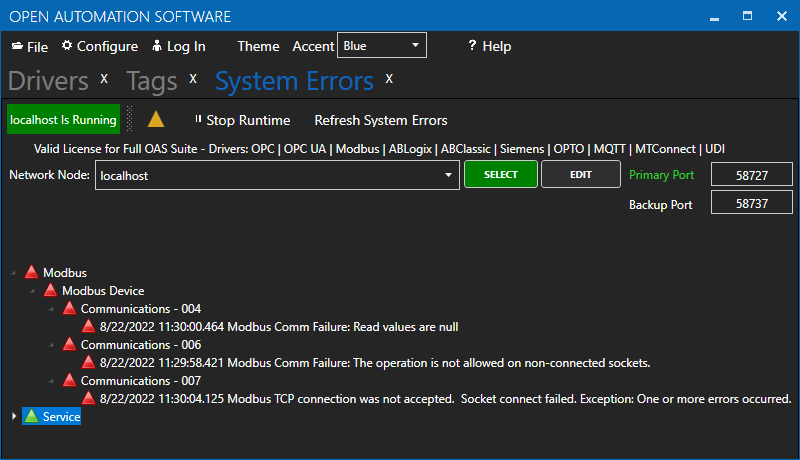
The information provided can often help you determine the cause of communication failures.
The history of all systems errors can be found in the OAS Error Log specified under Configure-Options-System Logging.
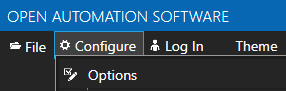
The default directory is the Log subdirectory in the OAS installation directory. On Windows the default location is C:\Program Files\Open Automation Software\OAS\Log\.
Example from log:
11:29:58.421 Modbus - Modbus Device - Communications - 006 - Modbus Comm Failure: The operation is not allowed on non-connected sockets.
11:30:00.464 Modbus - Modbus Device - Communications - 004 - Modbus Comm Failure: Read values are null
11:30:04.125 Modbus - Modbus Device - Communications - 007 - Modbus TCP connection was not accepted. Socket connect failed. Exception: One or more errors occurred.
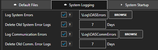
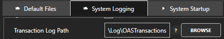
You can enable the Modbus transaction logging under Configure-Options-System Logging to verify the device is responding to a request and analyze the packet optimization for each memory and address defined in the tag configuration.
Optionally specify a specify a specific Driver Interface to capture with the property Driver Interface To Log or leave this blank to log all Modbus drivers.
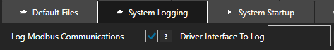
Specify the location of where the communication logs will be saved with the property Transaction Log Path further down in System Logging.
Following is an example from the log reading Holding Register 40001 with Zero Based Addressing.
12:10:12.944 ReadHoldingRegisters: Start Address: 0 Number of Points: 1
Wireshark is an excellent third party tool to analyze network communications over Ethernet. It has built in support for Modbus TCP and RTU protocols to convert the raw packets into easy to read Modbus protocol requests and responses. Select Analyze-Enabled Protocols to enable the Modbus protocols.
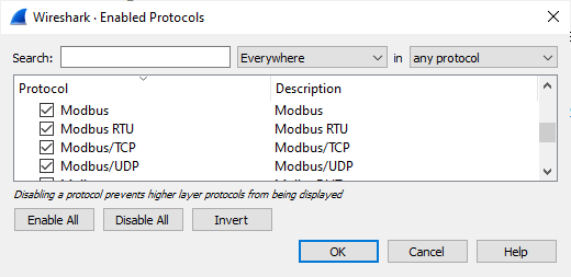
Use Apply a display filter field to filter the network traffic based on the IP address of the Modbus device you want to monitor with ip.addr == <IP address>, an example ip.addr == 192.168.0.1
You can download Wireshark from https://www.wireshark.org/download.html
ModScan32 is a good test application to communicate to Modbus devices to verify the device can respond to requests from the system.
You can download Modscan32 from WinTech Software Design.
If communication failures are intermittent due to weak radio signal or slow device response you can increase the Timeout and / or Number of Retries under Configure-Drivers.
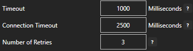
The default Timeout is 1000 milliseconds (1 second).
MyGroup.MyTag.ValueTag names are case sensitive and the current value of a tag would be .Value as the most common variable.
\\192.168.0.1\TagName.Value
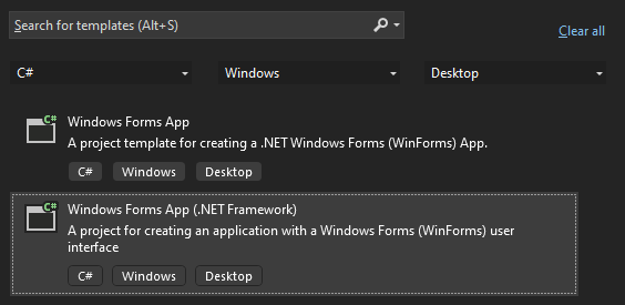 See the correct project type for WinForm above that is listed as Windows Forms App (.NET Framework) while Windows Forms App would not be the correct project type.
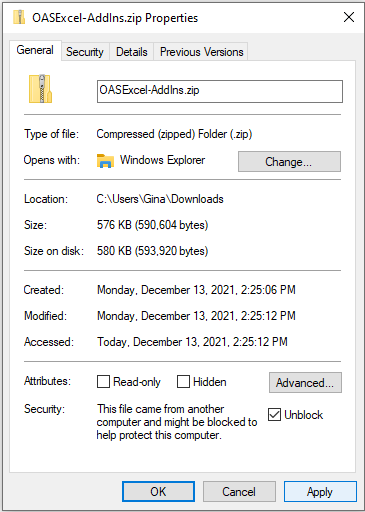
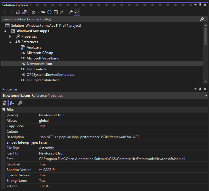 If the Path does not reference the OAS installation directory remove the reference and select to Add Reference and browse for dll from the respective directory for the specific product feature. For .NET Framework applications include the .dlls located in C:\Program Files\Open Automation Software\OAS\Controls\NetFramework\. The Target Framework set for the VS project must be .NET Framework 4.6.1 or greater. For .NET Standard supporting the following targets include the. dlls located in C:\Program Files\Open Automation Software\OAS\Controls\NetStandard\.
See a list of locations for the correct type in the troubleshooting type After updating to OAS Version 17 the project no longer compiles for a list of correct project reference paths for each type of Visual Studio Project.
If the Path does not reference the OAS installation directory remove the reference and select to Add Reference and browse for dll from the respective directory for the specific product feature. For .NET Framework applications include the .dlls located in C:\Program Files\Open Automation Software\OAS\Controls\NetFramework\. The Target Framework set for the VS project must be .NET Framework 4.6.1 or greater. For .NET Standard supporting the following targets include the. dlls located in C:\Program Files\Open Automation Software\OAS\Controls\NetStandard\.
See a list of locations for the correct type in the troubleshooting type After updating to OAS Version 17 the project no longer compiles for a list of correct project reference paths for each type of Visual Studio Project.
OAS version 17 implements an improved network interface which requires some additional assemblies.
All dependent .dlls are located in the relative subdirectory of the Controls directory of the OAS installation directory, typically C:\Program Files\Open Automation Software\OAS\Controls\.
To add a reference to a Visual Studio project right click on References in the Solution Explorer.
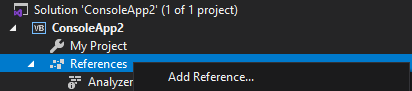
Select Browse to browse the directory for each application feature.
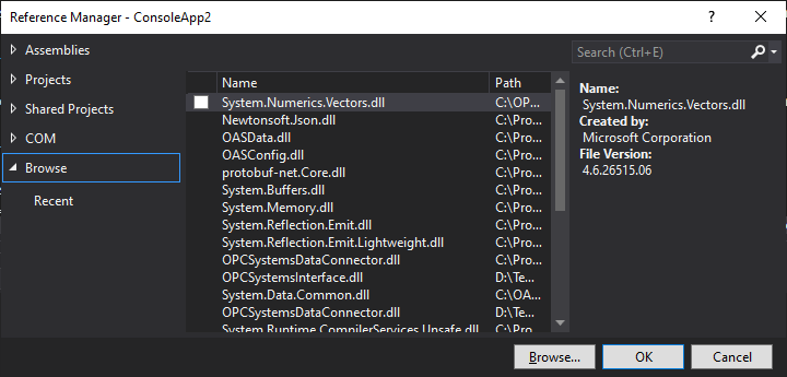
Include all .dlls files in the respective directory for the specific product feature.
For .NET Framework applications include the .dlls located in C:\Program Files\Open Automation Software\OAS\Controls\NetFramework\.
The Target Framework set for the VS project must be .NET Framework 4.6.1 or greater.
For .NET Standard supporting the following targets include the. dlls located in C:\Program Files\Open Automation Software\OAS\Controls\NetStandard\.
WPF HMI Assemblies
WinForm HMI Assemblies
Alarm .NET Assemblies
Trend .NET Assemblies
.NET Data Connector Assemblies
Server Configuration Assemblies
If there are errors executing a REST API call, you can check the OAS Configuration app, click on the triangle icon (should be flashing of there's an error) and you'll see system errors.
Locate the REST API and expand it out and you should see the failed calls. But it often won't give you the detailed HTTP request/response and just contain the failed URL that was attempted. It's a good way to see if people are hitting incorrect endpoints.
If you use Postman to execute REST API calls, you can see the proper URLs, headers, body contents, etc. for making proper calls.
If you ever get these response or codes, this is what they mean:
401: Unauthorized - you have not included the clientid and token fields in the request header, or the session has expired
500: Unknown server error - this may be something we need to investigate since the data was submitted properly but an error occurred on the server processing the request.
404: The object you're trying to GET or PUT (update) does not exist
If you see "Service Unavailable" that means the REST API did not start up properly.
If you see a message indicating the Endpoint does not exist, this means the URL is not correct for the call.
If there's something specific you're attempting and don't know what the issue is, you can always look at a successful call from Postman's console and it will expose everything in the request header/body and response header/body. You can compare it to your failing call to see what you might need, such as the correct Content-type. You can always let us know what call you're stuck on and we can investigate why it might not work for you.
How to identify and resolve communications errors with data sources.
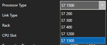
Below are some helpful troubleshooting steps to resolve bad data quality for tags with a Data Source of Siemens for communications to Siemens S7-200, S7-300, S7-400, S7-1200, and S7-1500 controllers.
![]()
Set the Processor Type of the Driver to match the controller S7-200, S7-300, S7-400, S7-1200, or S7-1500.
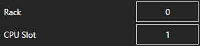
The Rack and CPU Slot number must be correctly set.
The Siemens driver commutates out of the default network adapter. View Set Default Network Adapter for Driver Interfaces to see how to set the default adapter on Windows.
If you encounter a System Error when using the Siemens Driver Interface of Function Not Supported you may need to setup the security in the PLC to access.
View the Siemens Security Setup article for the instructions to permit access.
When connecting to a controller the device will need to be reachable from the OAS system. Use Windows Command Prompt or Linux terminal where the OAS Engine is running to ping the device to verify it is reachable.
The Address field in each tag should be set to the correct memory variable that exists in the online controller.
![]()
View Siemens Address Syntax for the correct address assignment.
If an Address is incorrectly defined to something that does not exist in the controller a System Error will be posted under Configure-System Errors listing all addresses that are invalid.
Use CSV Export under Configure-Tags to open with MS Excel and to search for the tags that contain the invalid addresses that are listed. The System Errors are also logged to text files into the OAS Error Log directory specified under Configure-Options-System Logging.
If the System Error 0x00000005 – Address does not exist or is out of range appears under Configure-System Errors uncheck Optimized block access attribute of dbOptimized in the controller program and re-compile and upload to the controller.
Set the correct Siemens Data Type for the memory variable in the controller to match the data width used in the address.
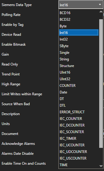
Data Width
|
Data |
Description |
Bits |
Supported |
|
X, |
Bit |
1 |
Boolean |
|
B |
Byte |
8 |
SByte, |
|
W |
Word |
16 |
Int16, |
|
D |
DWord |
32 |
Int32, |
For Unicode character support in strings set the data type to WString with a data width of W.
Also match the OAS tag Data Type to the correct value type to be set. If you are unsure of the data type use Object to see the result.
Note: If you are using Gain and Offset in a tag to scale an integer value to a floating point value use Double Float or Single Float as the Data Type.
If one or more of the Tags defined to the Driver Interface has invalid address defined or the address does not exist in the device the remaining good addresses can be affected with either taking the device offline or invalid packet request or response.
To isolate one or more tags to their own dedicated communication channel select the existing driver interface and change the name to a new unique name and select Add Driver.
![]()
To define a tag to the new driver select Configure-Tags, then select the tag you want to isolate to select the new driver interface.
Select Apply Changes.
![]()
If the data quality changes to good for the tag then resolve the other addresses in the tags defined to the first driver interface used.
![]()
To help you further identify which tag addresses are bad use the Tag Watch Window to view multiple tags in one window.
To add a tag to the Watch Window, select any tag or tag group and right click on it. Then choose Add to Watch from the context menu.
The tag you selected will then appear in the Watch Window.
If an address is defined that does not exist in the device other tags with valid addresses can also be affected if the address is grouped into the same communication packet request as the invalid address.
Once you identify which addresses are invalid investigate if the address exists in the device or refer to the controller program to find the correct addresses to use.
When the property Device Read is enabled polling communications will be disabled and read requests will only be performed when the tag defined for the Device Read transitions from false to true. If data is to be polled continuously from the device disable the tag property Device Read.
![]()
The Enable by Tag property is used to define a Boolean tag that will enable or disable communications for the tag. If data is to be polled continuously from the device disable the tag property Enable by Tag.
![]()
Use Configure-License to verify that the Driver Siemens is enabled.
Select Configure-System Errors and expand any Siemens Interface error to see the details of the error.
The information provided can often help you determine the cause of communication failures.
The history of all systems errors can be found in the OAS Error Log specified under Configure-Options-System Logging.
The default directory is the Log subdirectory in the OAS installation directory. On Windows the default location is C:\Program Files\Open Automation Software\OAS\Log\.
You can enable the Log AB and Siemens Comm. transaction logging under Configure-Options-System Logging to track communications with the Siemens controllers.
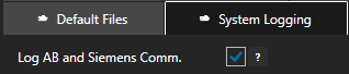
Specify the location of where the communication logs will be saved with the property Transaction Log Path further down in System Logging.
Wireshark is an excellent third party tool to analyze network communications over Ethernet.
Download WireShark from https://www.wireshark.org/
If communication failures are intermittent due to faulty network you can increase the Transaction Timeout under Configure-Drivers.
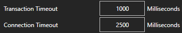
The default Timeout is 1000 milliseconds (1 second).
How to identify and resolve communications errors with data sources.
Below are some helpful troubleshooting steps to resolve common data logging errors.
Use Configure-License to verify that the Data Historian product feature is enabled.
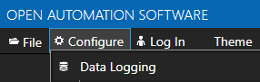
Select Configure-System Errors and expand any Data Log errors to see the details of the error.
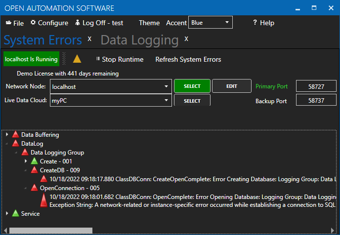
The information provided can often help you determine the cause of data logging failure.
The history of all systems errors can be found in the OAS Error Log specified under Configure-Options-System Logging.
You can enable Log Data Logging Transactions under Configure-Options-System Logging to track and record all transactions for each logging group.
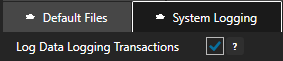
Specify the location of where the transaction logs will be saved with the property Transaction Log Path further down in System Logging.
All transactions will be recorded in the individual file for each logging group with the name of the file containing the logging group name.
The log will contain both any database errors and the values to be logged.
Example:
09:29:25.072 Tags and Values to be processed:
Tag: Ramp.Value
TimeStamp: 10/18/2022 09:29:25.000
Quality: True
Value: 65
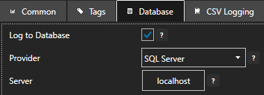
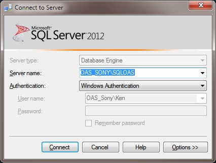
If the Server under the database tab is unreachable or incorrectly defined a System Error will indicate the database cannot be opened or created.
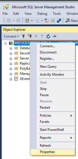
Use the database admin tool like SQL Server Management Studio, pgAdmin4, or other appropriate database tool to see if it can connect to the local or remote database engine from the system OAS is running on.
If Set Server Name with Tag is enabled verify that the value of the string tag defined is the correct server name. Try a static server name if so by disabling Set Server Name with Tag.
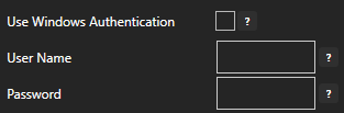
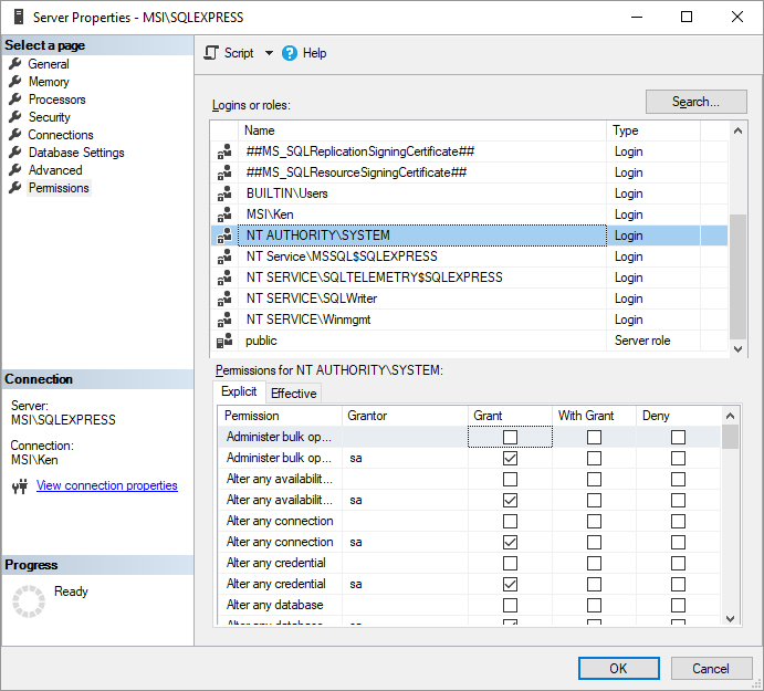
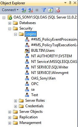
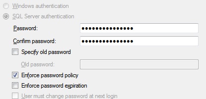
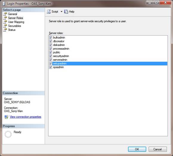
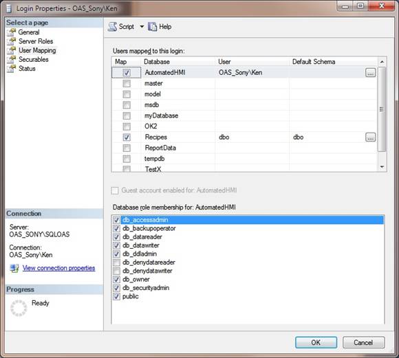
Set the correct User Name and Password credentials from the database engine with access to create databases, tables, and field names along with the rights to insert and update records.
![]()
If logging to SQL Server see Database Security Login to define login access in the database engine.
The logging group needs to be active in order to process values to the database or CSV file.
Verify that Logging Active is enabled under the Common tab of the logging group.
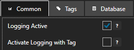
If Active Logging with Tag is enabled verify that the Boolean tag defined is true and good quality. Also verify that the tag and variable name is properly defined.
If the Logging Type is set to Event Driven, Event Driven Narrow, or Snapshot recording verify that the Trigger Tag is properly defined using the Browse button to an Integer or Boolean tag variable.
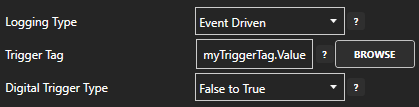
Also verify that the value of the Trigger Tag is changing state using Configure-Tags.
When there is an unresolved error data will be buffered to the Store and Forward directory specified under Configure-Options-Store and Forward.
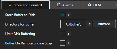
Check the directory specified for the store and forward location to see if any .dlb files are being buffered for the logging group. If there are files being go to Configure-System Errors to see what Data Log error is causing the data buffering.
Data from the buffered files will be the first to be processed and must be resolved to move onto the next set of data, so current data will not be able to be logged until the store and forward buffered files can be processed.
You can extract the contents of any buffer file with the Data Buffer to CSV program under the Open Automation Software program group.
To discard the data within the buffer files and move onto the next record there are 3 options.
![]()
A null value will be recorded to the database or CSV file under one of the following conditions.
Note: Tag names are case sensitive.
If one or more of the table columns has been modified to not allow null values in the field data will be buffered to the Store and Forward directory if the data quality of a tag to be logged is bad.
There are 2 solutions to resolve this conflict.
1. Change the field definition back to Allow Nulls. First check with the database admin to why it was change to not allow null values in case there is a downstream report depending on the data.
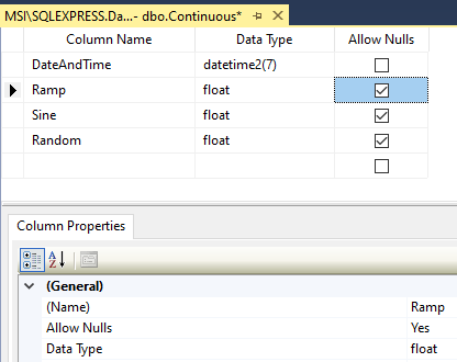
2. Enable the property Discard Null Rejects under the Database tab of the logging group.
![]()
If the table or field added is not automatically created in the database verify that Create Table and Fields is enabled under the Database tab of the logging group.
![]()
If setting up logging to a table that already exists verify that the either all of the fields are correctly defined with the right data type or the fields that are not being logged to allow null values.
If one or more database triggers is defined to a table note that the logging rate and reliability will be impacted by the trigger's ability to complete.
If data is not being logged or slow to arrive in the database with no System Error reported check the table in the database engine if there are Triggers defined. If there are Triggers check with the database admin if the triggers can be removed or revised to complete quickly and reliably.
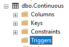
Note: If you need the Triggers to fire disable the bulk insert logging by setting the property Records to Enable Bulk Insert to 10000000.
![]()
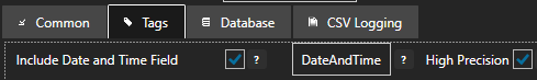
The DateAndTime field will record the timestamp from the data source. If tags being logged from an OPC server and the time delivered is different than the local CPU time this can be overridden to use the local CPU clock at the data source of the Tag by setting the property Use TimeStamp from OPC Servers under Configure-Options-OPC to false.
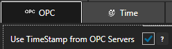
To view the timestamp of any tag go to Configure-Tags and select the tag or parent group and select Add to Watch. View the Watch Window article for an example of use.
It is not possible to log remote tag values from a different time zone using Continuous or Continuous Narrow with the local time. In this configuration data must be logged with UTC time. To enable UTC time enable the property Convert Timestamps to UTC under the Common tab.
![]()
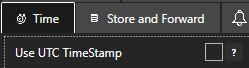
Another option is to set all tag values to UTC at the data source engine with the option Use UTC Timestamp under Configure-Options-Time.
By default the DateAndTime field defined under the Tags tab is set to High Resolution with 100 nanosecond resolution. When logging to older versions of SQL Server, Oralce, or mySQL and the System Error Cannot find data type DateTime2 is reported uncheck the property High Precision under the Tags tab of the logging group.
When logging to a CSV file store and forward will be enabled when Excel opens the CSV file currently logged to. Excel locks files for exclusive use when it has a file open. There will be no data loss during this time and all data will be logged when Excel closes the file.
Download and install the Microsoft Data Access Components 2.8.
https://www.microsoft.com/en-au/download/details.aspx?id=21995
The following update will correct this issue.
For Office 2010, the following update will correct this issue.
https://www.microsoft.com/en-us/download/details.aspx?id=39664
For Office 365 (please note, by default Office365 installs the 32-bit version regardless of your system), use:
https://www.microsoft.com/en-us/download/details.aspx?id=54920
 Select OK
How to identify and resolve communications errors with data sources.
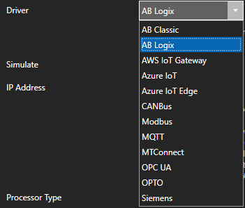
Below are some helpful troubleshooting steps to resolve bad data quality for tags with a Data Source of ABLogix and ABClassic for communications to Allen Bradley ControlLogix, CompactLogix, GuardLogix, Micro800, MicroLogix, SLC 500, and PLC-5 controllers.
![]()
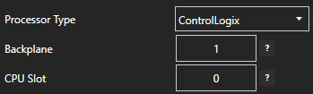
To communicate to ControlLogix, CompactLogix, GuardLogix, and Micro800 choose AB Logix for the Driver type. For MicroLogix, SLC 500, and PLC-5 choose AB Classic.
When communicating to ControlLogix processors the Backplane and Slot number must be correctly set.
The AB Logix and AB Classic drivers commutate out of the default network adapter. View Set Default Network Adapter for Driver Interfaces to see how to set the default adapter on Windows.
When connecting to a controller the device will need to be reachable from the OAS system. Use Windows Command Prompt or Linux terminal where the OAS Engine is running to ping the device to verify it is reachable.
The Address field in each tag should be set to a variable name or address that exists in the online controller.
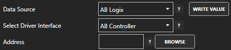
When interfacing with AB Logix controllers use the Browse button to select the correct address from the on-line controller.
See One Click Allen Bradley to automate setup of addressing from either online controllers or offline program files.
If an Address is incorrectly defined to something that does not exist in the controller a System Error will be posted under Configure-System Errors listing all addresses that are invalid.
Use CSV Export under Configure-Tags to open with MS Excel and to search for the tags that contain the invalid addresses that are listed. The System Errors are also logged to text files into the OAS Error Log directory specified under Configure-Options-System Logging.
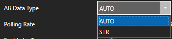
When using AB Logix the AB Data Type will need to be set to STR if the variable in the controller is a string. Set AB Data Type to AUTO for all other variable types.
Also match the OAS tag Data Type to the correct value type to be set. If you are unsure of the data type use Object to see the result.
Note: If you are using Gain and Offset in a tag to scale an integer value to a floating point value use Double Float or Single Float as the Data Type.
If one or more of the Tags defined to the Driver Interface has invalid address defined or the address does not exist in the device the remaining good addresses can be affected with either taking the device offline or invalid packet request or response.
If running on Windows you can identify which addresses are defined as invalid using the program AB_Tag_Validation.exe located in C:\Program Files\Open Automation Software\OAS\AB Validation\.
Note: if you do not see the AB Validation subdirectory update your version of OAS to the latest version.
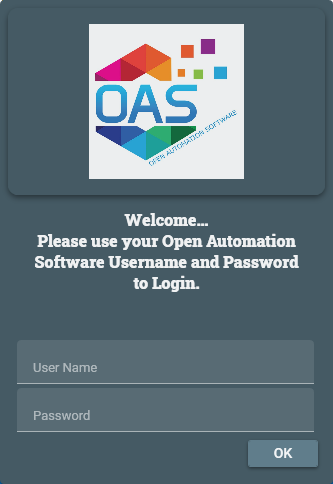
Run AB_Tag_Validation.exe and enter the admin username and password you have defined for OAS.
Select each Driver Interface in the Driver Interfaces list in the upper left to verify all tags defined to that Driver Interface.
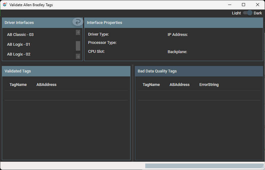
Any addresses that are defined incorrectly that do not exist in the controller will appear in the Bad Data Quality Tags folder along with the tag name that contains that address.
If running on Linux or Windows another way to identify the issue is to isolate one or more tags to their own dedicated communication channel select the existing driver interface and change the name to a new unique name and select Add Driver.
![]()
To define a tag to the new driver select Configure-Tags, then select the tag you want to isolate to select the new driver interface.
Select Apply Changes.
![]()
If the data quality changes to good for the tag then resolve the other addresses in the tags defined to the first driver interface used.
![]()
To help you further identify which tag addresses are bad use the Tag Watch Window to view multiple tags in one window.
To add a tag to the Watch Window, select any tag or tag group and right click on it. Then choose Add to Watch from the context menu.
The tag you selected will then appear in the Watch Window.
If an address is defined that does not exist in the device other tags with valid addresses can also be affected if the address is grouped into the same communication packet request as the invalid address.
Once you identify which addresses are invalid investigate if the address exists in the device or refer to the controller program to find the correct addresses to use.
When the property Device Read is enabled polling communications will be disabled and read requests will only be performed when the tag defined for the Device Read transitions from false to true. If data is to be polled continuously from the device disable the tag property Device Read.
![]()
The Enable by Tag property is used to define a Boolean tag that will enable or disable communications for the tag. If data is to be polled continuously from the device disable the tag property Enable by Tag.
![]()
Use Configure-License to verify that the Driver ABLogix or ABClassic is enabled.
Select Configure-System Errors and expand any AB or Driver Interface error to see the details of the error.
The information provided can often help you determine the cause of communication failures.
The history of all systems errors can be found in the OAS Error Log specified under Configure-Options-System Logging.
The default directory is the Log subdirectory in the OAS installation directory. On Windows the default location is C:\Program Files\Open Automation Software\OAS\Log\.
You can enable the Log AB and Siemens Comm. transaction logging under Configure-Options-System Logging to track .
Specify the location of where the communication logs will be saved with the property Transaction Log Path further down in System Logging.
Wireshark is an excellent third party tool to analyze network communications over Ethernet.
Download WireShark from https://www.wireshark.org/
If communication failures are intermittent due to faulty network you can increase the Transaction Timeout under Configure-Drivers.
The default Timeout is 1000 milliseconds (1 second).