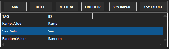
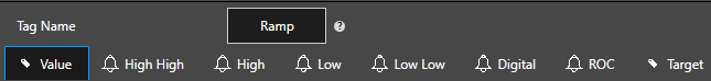
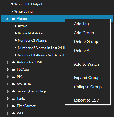
Tag Name
The Tag Name is used to identify the specific point and all of its parameters. The Tag can be included within a Group.
For example the following would be the full path for a Tag within a Group:
- myGroup.myTag
- The client applications will reference the tag name and parameter by name.
- myGroup.myTag.Value, myGroup.myTag.AlarmStatusHighHigh, or myGroup.myTag.ValueTimeOn.
Data Type
The data type of a Parameter can be set to one of the following types:
- Double Float (64 bit)
- Unsigned Byte (8 bit)
- Integer (32 bit)
- Unsigned Long Integer (64 bit)
- Array Double (64 bit)
- Array Bool
|
- Single Float (32 bit)
- Short Integer (16 bit)
- Unsigned Integer (32 bit)
- Boolean
- Array Integer (32 bit)
- Object Type (Any custom object, array, or structure)
|
- Signed Byte (8 bit)
- Unsigned Short Integer (16 bit)
- Long Integer (64 bit)
- String
- Array Single (32 bit)
- Array Byte (8 bit)
|
Reset Value to False
When enabled for a Boolean Tag a write of False will be sent immediately when the value transitions from False to True.
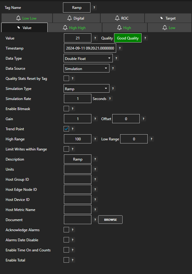
Trend Point
Enable Trend Point to have the Parameter available for trending from OAS Trend .NET and OAS Web Trend. You can data log a Parameter value without trending the point if desired.
Value
The current value of the Parameter. The source of the Value is determined by the Data Source. If the Data Source is set to Value this remains fixed and can be changed directly. All other Data Sources will determine what the Value is.
Gain
The Gain is a multiplier to the raw incoming value except when the Data Source is Value:
Value = RawValue * Gain + Offset
When writing to an OPC Item the calculation is reversed:
OutputValue = (Value – Offset) / Gain
Offset
The Offset is an addition to the raw incoming value except when the Data Source is Value:
Value = RawValue * Gain + Offset
When writing to an OPC Item the calculation is reversed:
OutputValue = (Value – Offset) / Gain
High Range
The default Y Axis Range High for a trend pen.
Low Range
The default Y Axis Range Low for a trend pen.
Read Only
The value of the parameter cannot be written to.
Out Of Range
The limit if the value exceeds the alarm will be disabled.
An example is the High Alarm Limit is set to 80 and the Out Of Range is set to 1000:
- If the Value is below 80 there is no alarm.
- If the Value is greater than 80 and less than 1000 the tag is in a High Alarm State.
- If the Value is 1000 or greater there is no alarm.
Alarm Limit
The current value of the alarm limit Parameter. The source of the Alarm Limit is determined by the Data Source. If the Data Source is set to Value this remains fixed and can be changed directly. All other Data Sources will determine what the Alarm Limit is.
ROC Alarm Type
There are three (3) Rate of Change alarm types:
- Negative And Positive alarms on a rise or fall of the value by more than the limit.
- Negative Only alarms on a fall of the value by more than the limit.
- Positive Only alarms on a rise of the value by more than the limit.
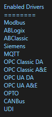
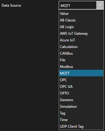
Data Source
The source of where the value will come from. The Data Source can be set to one of the following types:
- Value: Fixed value that can be set in configuration or from any client.
- AB Classic: Communications to Allen Bradley MicroLogix, SLC 500, and PLC-5.
- AB Logix: Communications to Allen Bradley ControlLogix, CompactLogix, GuardLogix, and Micro800.
- AWS IoT Gateway: Amazon Web Services IoT Gateway.
- Calculation: Math equation with multiple tag parameters as a data source. The result is read only and cannot be written to. View the following video to see how to define a Calculation.
- CANBus: CanBus interface.
- Database: Read and update database individual column of record in table field name and where statement to specify which record.
- File-Binary: Reads value from binary file with the file name of the full tag path and parameter name and extension .bin located in the ConfigFiles directory. When value is written to Tag the file will be updated with new value.
- File-Text: Reads value from text file with the file name of the full tag path and parameter name and extension .txt located in the ConfigFiles directory. When value is written to Tag the file will be updated with new value.
- File-XML: Reads value from xml file with the file name of the full tag path and parameter name and extension .xml located in the ConfigFiles directory. When value is written to Tag the file will be updated with new value.
- GPIO: General Purpose Input Output for Raspberry Pi.
- JSON: Tag values generate JSON key value pairs.
- Kafka: Communications to Kafka clusters.
- Modbus: Modbus master communications for Modbus TCP, Modbus RTU, and Modbus ASCII all supported on both Ethernet and Serial interfaces.
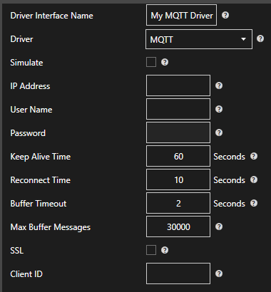
- MQTT: Communications to MQTT brokers to send and receive data to MQTT devices and software.
- MTConnect: Automated tag creation and live value update from MTConnect.
- OPC: Value from Classic DA 2.XX or 3.0 OPC Server.
- OPC UA: OPC UA Server.
- Siemens: Communications to Siemens S7-200, S7-300, S7-400, S7-1200, and S7-1500.
- Simulation: Dynamic simulation of data.
- Sparkplug B: Communications to Sparkplug B MQTT brokers to send and receive data to Sparkplug B devices and software.
- Tag: Value is from another tag parameter from the same service or remote service. The result is read only and cannot be written to.
- Time: Date and time from the CPU clock.
- Year: The current year as an Integer. Value is read only.
- Month: The current month as an Integer. Value is read only.
- Day: The current day as an Integer. Value is read only.
- Hour: The current hour as an Integer. Value is read only.
- Minute: The current minute as an Integer. Value is read only.
- Second: The current second as an Integer. Value is read only.
- SecondToday: The total number of seconds elapsed in the current day as an Integer. Value is read only.
- Weekday: The current weekday as an Integer. Value is read only. 0 = Sunday, 1 = Monday, 2 = Tuesday, 3 = Wednesday, 4 = Thursday, 5 = Friday, 6 = Saturday.
- WeekdayName: The current weekday as a String. Value is read only.
- DateTimeString: The current date and time as a String. Value is read only.
- UTCYear: The current Universal Time Code year as an Integer. Value is read only.
- UTCMonth: The current Universal Time Code month as an Integer. Value is read only.
- UTCDay: The current Universal Time Code day as an Integer. Value is read only.
- UTCHour: The current Universal Time Code hour as an Integer. Value is read only.
- UTCMinute: The current Universal Time Code minute as an Integer. Value is read only.
- UTCSecond: The current Universal Time Code second as an Integer. Value is read only.
- UTCSecondToday: The total number of seconds elapsed in the current Universal Time Code day as an Integer. Value is read only.
- UTCWeekday: The current Universal Time Code weekday as an Integer. Value is read only. 0 = Sunday, 1 = Monday, 2 = Tuesday, 3 = Wednesday, 4 = Thursday, 5 = Friday, 6 = Saturday.
- UTCWeekdayName: The current Universal Time Code weekday as a String. Value is read only.
- UTCDateTimeString: The current Universal Time Code date and time as a String. Value is read only.
- UDPClientTag: Remote tag from another service that is setup for UDP Broadcast. Value is read only.
Tag Data Source
Path of the Tag and Parameter for the value if the data source is selected as Tag. This can be tag value from a remote service with the syntax of \Network Node or IP AddressTag.Value.
Source When Bad
Allows the value and data quality to be overridden when the value quality is bad when the Data Source is set to OPC Item, Tag, Calculation, or UDP Client Tag.
The following are the three (3) available options for Source When Bad:
- Normal Bad Quality: When the data source is bad quality the result is bad quality. With Calculations any one of the source tags in the calculation being bad quality will cause the result to be bad quality.
- Set Sources To Default Value: When the data source quality is bad the source value is overridden to be what is set as Default Value with the data type of Default Value Type. With Calculations that have multiple tag parameters as a source each individual tag value in the calculation will be set to the Default Value when its individual data quality is bad. This will result in the calculation performing the equation with the remaining actual values with tags with good quality and overriding the values for the tags that are bad quality.
- Hold Sources To Last Good Value: When the data sources quality changes to bad quality the last good value will be used as the data source. With Calculations that have multiple tag parameters as a source each individual tag value in the calculation will be held with its last good value when its individual data quality is bad. This will result in the calculation performing the equation with remaining actual values with tags with good quality and overriding the values for the tags that are bad quality with each individual tags last good quality.
- Set Sources To Tag Value: When the data sources quality is bad the value from another Open Automation Software Tag will be used. With Calculations that have multiple tag parameters as a source each individual tag value in the calculation will be set from the other Tag value. This will result in the calculation performing the equation with remaining actual values with tags with good quality and overriding the values for the tags that are bad quality with the assigned tag’s value.
Source Tag On Bad Quality
When Source When Bad is set to Set Sources To Tag Value this is the tag parameter to use for the value to set the source when the data quality is bad.
Default Value Type
The data type to use when the Source When Bad is set to Set Sources to Default Value. See Source When Bad for full description.
Default Value
The value to use when the Source When Bad is set to Set Sources to Default Value. See Source When Bad for full description.
Override OPC Quality On Bad Quality
Forces the OPC Quality that is passed onto the OPC Systems.NET OPC Server to good quality when the Data Source When Bad Quality is set to something other than the default of Normal Bad Quality and the Data Source is set to an OPC Item.
OPC Update Rate
Update rate of the OPC Item for the value if the data source is selected as OPC Item.
Keep OPC Item On Scan
With this option selected the communications to the OPC Item will always be enabled unless the Device Read option is selected.
When this option is disabled communications to the OPC Item will be enabled only when one or more clients are requesting the value from the Tag. If the point is trended, enabled for alarm monitoring with any one of the alarm limits enabled, or set as a Target output to another OPC Item this OPC Item will always be on scan regardless if there is a requesting client.
Note: Not recommended for OPC Items from RS-Linx OPC Server as it does not handle dynamic adding and removing items well.
OPC Access Path
OPC Access Path of the OPC Item for the value if the data source is selected as OPC Item. Most OPC Servers do not require this parameter, only servers that need to have a special topic like old DDE servers that have been converted to support OPC.
OPC Enable by Tag
When this option is enabled a Boolean Tag is defined to enable or disable OPC asynchronous communications.
Note: For standard asynchronous communications this should not be enabled.
Device Read
When enabled the Boolean Tag that is specified will cause a one-time read of OPC data when it transitions from False to True. Also when this attribute is enabled the normal asynchronous connection is disabled and the item is only polled on the transition from False to True for the Device Read Tag specified.
When a read is performed it informs the OPC Server to do a Device Read from the device to obtain the very latest value at that time.
Note: For standard asynchronous communications this should not be enabled.
OPC Enumerate
This is a list of string values returned from the OPC Server Browse that represent the specific meaning for each integer value that is returned from the OPC Item.
The string arrays are separated by a pipe character ‘|’.
Enumerate Index
If the integer value for OPC Enumerate does not begin with 0 or is not continuous numbers to convert to the string array for OPC Enumerate you can enable Enumerate Index to provide an index array of integer values to convert to.
Following is an example:
- The value 123 should result in the string value Test0.
- The value 456 should result in the string value Test1.
- The value 789 should result in the string value Test2.
- All other values will result in bad quality.
- In OPC Enumerate specify Test0|Test1|Test2
- In Enumerate Index specify 123|456|789
- The integer arrays are separated by a pipe character ‘|’.
Description
Description of the Tag used as the default Trend Pen Description.
Also used as the default Alarm Text when an Alarm Limit is first enabled.
Units
Engineering Units of the Tag used as the default Trend Pen Units.
Document
This is typically a URL path to launch a document that is sent to the Windows and Web alarm windows when an alarm occurs. It can also be used for your own document purposes as a string to launch other documents from a .NET or web application.
Enable Alarm
Select each desired alarm limit to enable the alarm evaluation.
Alarm Enable With Tag
This property allows a Boolean Tag to be defined that will control if the Alarm Limit is enabled or disabled.
Alarm Group
Used in .Net Alarm and Web Alarm components and alarm logging for filtering alarms based on group. Simply enter the new alarm group or select from the existing list of groups. OPC, System, and Tag Client are default alarm groups used to identify system and communication alarms.
Alarm Priority
Used in .NET Alarm and Web Alarm components and alarm logging for filtering alarms based on priority. The valid range is from 0 to Int32.Max.
Deadband
For Analog Alarm Limits the amount that the value must be within the limit before the alarm condition is cleared.
Time Delay
The time delay in seconds that the alarm condition must remain active before the alarm is posted as an active alarm. The date and time when the alarm first became active is used as the alarm date and time, not the date and time it was posted as an active alarm.
If you would like the AlarmStatus parameter to be set immediate and not wait for the Time Delay use Configure-Options to set Update Alarm Status Immediately without Alarm Time Delay.
Alarm Text
Description of the Tag used as the alarm text when the alarm is active.
Also used as the Alarm Text for .NET Alarm and Web Alarm components and Alarm Logging.
The Alarm Text can be fixed or dynamic with the Dynamic Alarm Text attribute.
Dynamic Alarm Text
The Alarm Text of an alarm message can be dynamic based on other Tag values.
The following options can be used for changing the Alarm Text:
- Static Alarm Text: No change to the alarm text is performed, the default Alarm Text is used.
- Prepend Alarm Text: Adds the value of the dynamic alarm text tag ahead of the base Alarm Text.
- Overwrite Alarm Text: Replaces the alarm text entirely with the value of the dynamic alarm text tag.
- Append Alarm Text: Appends the value of the dynamic alarm text after the base Alarm Text.
When the alarm occurs the current value of the alarm message is locked for that instance of the alarm so when it is acknowledged or it clears the message is the same for all states.
Alarm Text Append True
The text that can be appended to the static or dynamic alarm text for a Digital Alarm Limit when the value is true.
Alarm Text Append False
The text that can be appended to the static or dynamic alarm text for a Digital Alarm Limit when the value is false.
Log As Event
When the Value reaches the alarm limit the event will not be indicated and recorded as an alarm with acknowledge state, but instead as an event that just records the one instance of when it reaches the alarm limit.
Time Stamp Offset
The amount of time to offset the alarm timestamp to match a particular time zone. If you prefer to use Universal Time Code enable the property Use UTC Timestamp under Configure-Options.
Daily Disable
Disable the alarm daily between the Start Hour and Minute and the End Hour and Minute.
Date Disable
Disable the alarm between the Start date and End date.
Units / Hour
The alarm limit for Rate of Change alarms that is specified in Units per Hour.
Use the Sample Rate to determine how frequently to compare the rate of change.
Sample Rate
The sampling rate in seconds on how frequently the rate of change alarm is evaluated.
Acknowledge Alarm Groups
Enable this feature to automatically acknowledge all alarms defined to the alarm groups defined in the property Alarm Groups to Acknowledge. The alarms are acknowledged when the Tag Value transitions from False to True.
If the Tag Value remains True no further acknowledge will occur until the value goes to False and then True again. If you desire to acknowledge all alarms in the local service leave the Alarm Groups to Acknowledge field blank.
Alarm Groups To Acknowledge
When the Acknowledge Alarm Groups property is enabled this is the list of Alarm Groups that will determine which alarms will be acknowledged automatically when the Tag Value transitions from False to True. If you desire to acknowledge all alarms in the local service leave this field blank.
Target Enable Write to OPC Item
Enables the OPC Route feature to send the Tag Value to an OPC Item.
This feature is not required to just write to an OPC Item from a client application. If the Data Source of a Tag is set to OPC Item and write occurs to the Tag the OPC Item will be written to.
The Target feature is mainly used to transfer values from OPC Servers to other OPC Servers or Calculation results to OPC Servers. Often used for remote data transfer over the Internet from OPC Server to OPC Server.
Target OPC Item
The OPC Item to write the Tag Value to.
Target Update Rate
The OPC Update Rate for the Target OPC Item.
Target OPC Access Path
The OPC Access Path of the OPC Item to write the Tag Value to. Most OPC Servers do not require this parameter, only servers that need to have a special topic like old DDE servers that have been converted to support OPC.
Target Float Deadband
For floating point values this is the amount to compare with current value from OPC Item and if within range it does not write a new value. If the source Value is different than the current Target OPC Item value by more than the Float Deadband a write will occur.
Target Write Continuously
When this property is disabled writes will only occur when the source Value is different than the target OPC Item.
When this property is enabled writes will continuously be performed at the rate of Target Write Continuously Frequency even if the source Value is the same as the target OPC Item value.
Note: When this feature is changed either the source Value must change or restart the service for the parameter to take effect.
Target Write Continuously Frequency
The rate at which the value is written to the destination if the continuous writing is enabled.
When this property is enabled writes will continuously be performed at the rate of Target Write Continuously Frequency.
Note: When this feature is changed either the source Value must change or restart the service for the parameter to take effect.

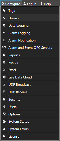
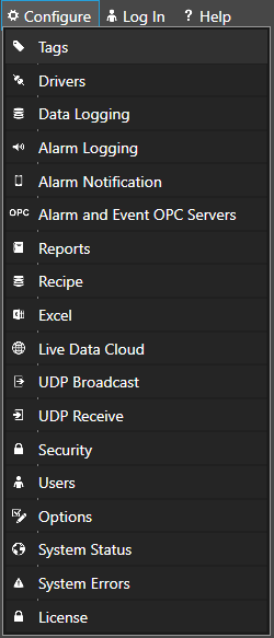
 Start Configure OAS application from the program group Open Automation Software.