View the OAS / System Integrator Partner Program page for a list of advantages OEMs have using OAS to automate setup and deployment of their system and increase availability of their customer’s data.
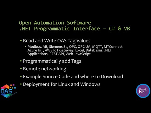
Videos – GPIO

IIoT Example Service Code
The OAS Example Service code example is a great way to learn how to programmatically add tags, update tag properties, and read and write live data to an OAS Engine.
You can view the .NET Programmatic Interface video for demonstration of the OAS Example Service Code and explanation of use of the most common methods.
- 00:00 – Introduction
- 00:33 – Source code example
- 01:07 – Visual studio projects example
- 01:33 – How to get a visual studio app
- 01:40 – How to create projects and use visual studio
- 03:05 – OAS service code example
- 15:00 – Tag variables
- 15:37 – How to browse tags
- 17:10 – Networking
- 20:55 – How to implement security
- 21:31 – How to publish
- 22:15 – How to register service
- 23:41 – How to change project name
- 26:20 – Questions
Download the OAS Example Service code.
Right click on the zip file that you have downloaded and choose Properties to select Unblock checkbox if Security warning is shown.
There are 4 Visual Studio projects all use the same methods to provide a working example.
- C# .NET Core Console App
- VB .NET Core Console App
- C# Windows Service
- VB Windows Service
These projects use the OASConfig.dll and OASData.dll assemblies that are included in the OAS platform installation directory, the default is C:\Program Files\Open Automation Software\OAS.
These projects are a good starting point if you need to setup unattended execution of processing and transferring data. They can be easily modified to include your own routines.
Note: It is recommend to run Visual Studio in Administrative mode for full access to project files. Either modify the properties of the shortcut under Advanced button or right click on the VS shortcut to Run as administrator.
Key Methods
Constructor
private OASData.Data oasd = new OASData.Data();
private OASConfig.Config oassys = new OASConfig.Config();
Create Tags
string DemoErrorString = "";
string DemoResultString = oassys.SetTagProperties(DemoPropertyValues, "localhost", ref DemoErrorString);
- PropertyValues is an array of arrays
- NetworkNode is optional and can be an IP Address network node, or registered domain name
- ErrorString will set the string passed by reference with Success if successful, or an error string if the tags were not created or updated.
First element is an array containing the property names. These property names will match the Tag CSV Export header.
object[] DemoDesiredColumns = new object[5];
DemoDesiredColumns[0] = "Tag"; // Required
DemoDesiredColumns[1] = "Value - Data Type";
DemoDesiredColumns[2] = "Value - Source";
DemoDesiredColumns[3] = "Value - Simulation Type";
DemoDesiredColumns[4] = "Value - Simulation Rate";
DemoPropertyValues[0] = DemoDesiredColumns; // First record is the header
Additional elements contain the values for each Tag.
object[] DemoTagValues1 = new object[5];
DemoTagValues1[0] = "OAS Demo Service.Source Tags.Ramp";
DemoTagValues1[1] = "Double";
DemoTagValues1[2] = "Simulation";
DemoTagValues1[3] = "Ramp";
DemoTagValues1[4] = 0.25;
DemoPropertyValues[1] = DemoTagValues1;
Write Tags Asynchronously
oasd.WriteTags(OASTags, OASValues);
- Tags is a string array of tag names and variables.
- Values is an object array containing the values to write to each tag.
- TimeStamps array can optionally be provided to set the time of the value if the Data Source of the Tag is Value.
If the Data Source is defined to a device or application writes to .Value will be written to the source defined.
Examples: Modbus, Siemens, AB, OPC UA, MQTT
Read Tags Asynchronously
Call AddTags to add a list of tags for subscription.
oasd.AddTags(ReadTags);
- Tags is a string array of tag names and variables.
Values will be returned in the ValuesChangedAll event anytime value changes in a tag variable.
oasd.ValuesChangedAll += OASDValuesChangedAll;
private void OASDValuesChangedAll(string[] Tags, object[] Values, bool[] Qualities, DateTime[] TimeStamps)
Call RemoveTags to remove any of the tag variables from subscription.
Write Tags Synchronously
SyncWriteTags is a blocking call that waits for the call to return from the service.
Errors = oasd.SyncWriteTags(Tags, Values);
- Tags is a string array of tag names and variables.
- Values is an object array containing the values to write to each tag.
- Errors is an Integer array that returns
- 0 when successful
- 1 when OAS Engine is not reachable
- 2 when the Tags array size is not equal to the Values array
Write Tags Synchronously with Confirmation
SyncWriteTagsWithConfirmation is a blocking call that waits for the values of the tag variables written call to return from the service.
Errors = oasd. SyncWriteTagsWithConfirmation(Tags, Values, 10000, 0.0001);
- Tags is a string array of tag names and variables.
- Values is an object array containing the values to write to each tag.
- Include optional timeout with default of 10,000 milliseconds and deadband for floating point values with default of 0.0001.
- Errors is an Integer array that returns
- 0 when successful
- 1 when OAS Engine is not reachable
- 2 when the Values array is null
- 3 when the Tags array size is not equal to the Values array
Read Tags Synchronously
SyncReadTags is a blocking call that obtains the current value of the list of tag variables.
Values = oasd.SyncReadTags(Tags, ref Errors, 10000);
- The returned value is an object array with the values for each tag variable.
- Tags is a string array of tag names and variables to read.
- Errors is an integer array returning:
- 0 if the tag variable quality is good
- 1 if the quality is bad
- 2 if the value could not be returned within the timeout specified
- Timeout is specified in milliseconds to wait for the call to return.
Networking
Tag names can include an IP Address, network node name, or registered domain name if the application is deployed remote from the OAS Engine.
Basis Networking Example:
\\192.168.0.1\TagName.Value
If Live Data Cloud networking is implemented for self-hosting with a dynamic IP Address the LDC syntax is applicable.
Live Data Cloud Networking Example:
\\www.opcweb.com\RemoteSCADAHosting.MyLDCNode.TagName.Value
Register Service
Linux
- Linux: Setup as user service or daemon
- Publish as Self-Contained
- chmod 755 ./OASCoreDemoService
- Test run with ./OASCoreDemoService
- See how to setup a .NET Core Console App as a daemon
Windows
- Windows: Use InstallUtil to register service
- Using Visual Studio Command Prompt as Administrator
- InstallUtil OASDemoService.exe
To change the name of the service set the properties of ServiceInstaller1 in ProjectInstaller.
- Description
- DisplayName
- ServiceName
See our OASConfig documentation and OASData documentation for more details.
Getting Started Raspberry Pi GPIO
The Open Automation Software platform has a built in communication driver for General Purpose Input / Output when deployed on a Raspberry Pi 4. Tags can be defined to read or write to GPIO pins.
You can view the OAS GPIO Setup Video to familiarize yourself with the following steps to setup GPIO communications on your Raspberry Pi 4.
- 00:00 – Introduction
- 00:11 – GPIO Driver
- 00:16 – Written tutorial
- 00:28 – Download and Install OAS on the Raspberry Pi
- 00:53 – OAS for Linux Download
- 01:06 – Set Up Access to the GPIO Driver
- 01:48 – Reboot the System
- 01:55 – Configure the Pins
- 03:05 – Configure more tags options
- 03:32 – Knowledge Base
- 03:45 – Save changes to tag configuration
- 04:24 – Transfer data
- 05:07 – Learn More
The following steps can be used to setup communications with the GPIO pins.
Step 1 – Installation
Download and install OAS onto Raspberry Pi 4 device. View the Raspberry Pi Installation guide for an easy to following video instructions or use the Linux Installation guide for step by step instructions to use the simple install script.
Step 2 – Set Access Level
Setup access to gpiomem for the user account the OASEngine is running under. The default is oasuser.
This is achieved by adding a rules file to etc/udev/rules.d/.
Log in to the root account and change directory to etc/udev/rules.d/.
ssh ubuntu@<ip address of Raspberry Pi>
cd /etc/udev/rules.d/
Create a file oas-gpio.rules with an editor with the following contents, then save the file.
SUBSYSTEM=="gpio*", PROGRAM="/bin/sh -c 'chown -R root:oasuser /dev/gpiomem && chmod -R 660 /dev/gpiomem'"
To create and edit the file you can use nano.
sudo nano oas-gpio.rules
Reboot the system.
sudo reboot
Step 3 – Configure Tags

From a Windows system start Configure OAS application from the program group Open Automation Software.
Select Configure-Tags.
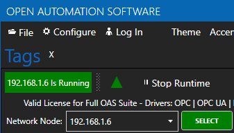
Enter the IP Address of the Raspberry Pi device and click Select.
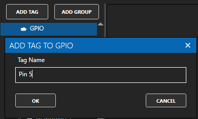
Select ADD GROUP to add the group GPIO and click OK. The group name can be anything you like, in this example it will be GPIO.
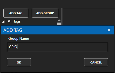
With the GPIO group selected click on ADD TAG to a tag with the name Pin 5. The tag name can be anything you desire. In this example we are assigning to GPIO Pin 5 so we will name it Pin 5.
Change the Data Type of the tag to Boolean.
Change Data Source Tag property to GPIO.
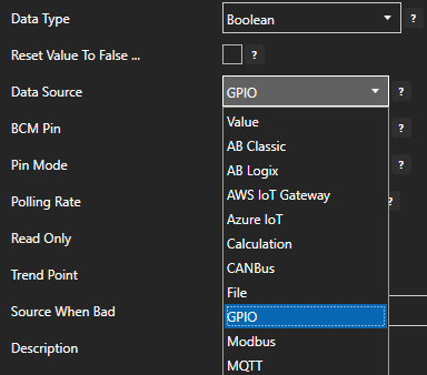
Set the Pin Mode to one of the following.
Input: Read Only – Configures the GPIO pin in floating mode, with high impedance.
InputPullDown: Read Only – Configures the GPIO pin as high impedance with a pull-down resistor to ground.
InputPullUp: Read Only – Configures the GPIO pin as high impedance with a pull-up resistor to the voltage charge connection (VCC).
Output: Write Only – Configures the GPIO pin in strong drive mode, with low impedance.
Note: A pin cannot be set to both Input and Output. Inputs are read only. Outputs are write only.
When defining the pin as an input set the desired Polling Rate for the update speed.
Select Apply Changes to activate the pin communications.

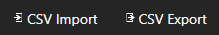
To define multiple tags use the CSV Export and CSV Import on the toolbar in the upper right together with Microsoft Excel.
NOTE: Tags can also be programmatically assigned with the OAS REST API or .NET Server Configuration interface.
Step 4 – Save GPIO Tags
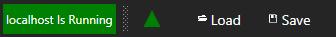
Select the Save button on the toolbar at the top.
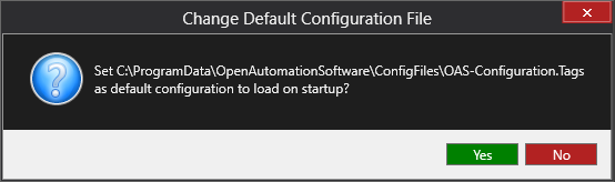
Enter a file name to be saved in C:\ProgramData\OpenAutomationSoftware\ConfigFiles directory on Windows or ConfigFiles subdirectory on Linux.
When prompted to set the file as the default configuration to load on startup select Yes.
The tags defined are now ready for use in all OAS features like Data Logging, Data Route, and Open UIEngine.
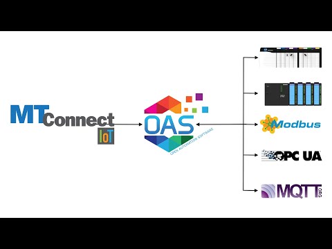
Videos – MTConnect


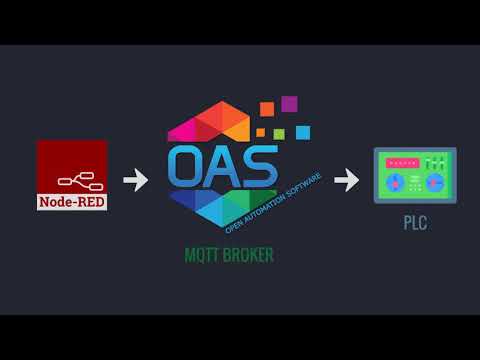
Videos – Node Red
Driver Interface Failover – Communication Redundancy
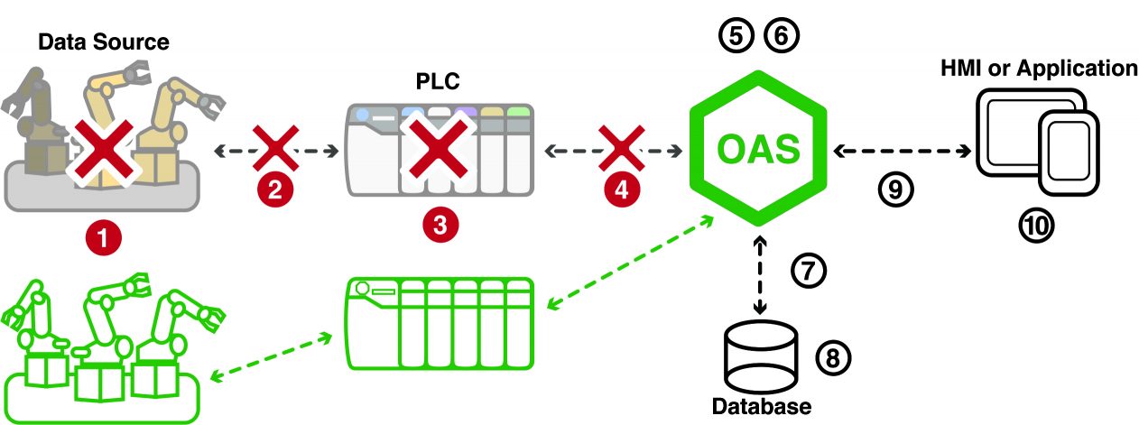
Overview
![]()
Each Interface can optionally enable a failover connection if the primary connection fails.
View the following video to see how Driver Interface Failover is setup and to see it in action with Modbus.
AB Classic Failover
![]() To define a backup AB controller enable the property Enable Failover under Configure-Drivers and set the IP Address of the secondary controller that would have the same variable addresses as the primary controller.
To define a backup AB controller enable the property Enable Failover under Configure-Drivers and set the IP Address of the secondary controller that would have the same variable addresses as the primary controller.
If both the primary and secondary controllers are offline the time to check for online status is Return to Online.
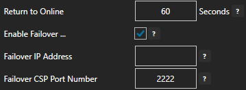
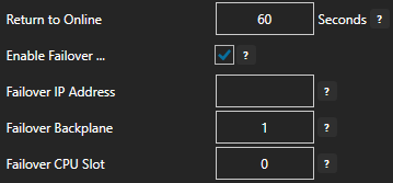
AB Logix Failover
![]() To define a backup AB controller enable the property Enable Failover under Configure-Drivers and set the IP Address, Backplane, and CPU Slot of the secondary controller that would have the same variable addresses as the primary controller.
To define a backup AB controller enable the property Enable Failover under Configure-Drivers and set the IP Address, Backplane, and CPU Slot of the secondary controller that would have the same variable addresses as the primary controller.
If both the primary and secondary controllers are offline the time to check for online status is Return to Online.
AWS IoT Gateway Failover
![]() To define a backup AWS server enable the property Enable Failover and set the Certificate and Private Key file paths and the IoT End Point to use.
To define a backup AWS server enable the property Enable Failover and set the Certificate and Private Key file paths and the IoT End Point to use.
If both the primary and secondary end points are not reachable the time to check for online status is Return to Online.
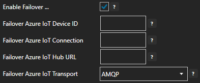
Azure IoT Failover
![]() To define a backup Azure server connection enable the property Enable Failover under Configure-Drivers and set the Azure IoT Device ID, IoT Connection, IoT Hub URL, and IoT Transport.
To define a backup Azure server connection enable the property Enable Failover under Configure-Drivers and set the Azure IoT Device ID, IoT Connection, IoT Hub URL, and IoT Transport.
If both the primary and secondary connections are not reachable the time to check for online status is Return to Online.
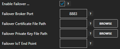
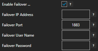
MQTT Failover
![]() To define a backup MQTT broker enable the property Enable Failover under Configure-Drivers and set the IP Address, Port, and optional User Name and Password for the backup broker.
To define a backup MQTT broker enable the property Enable Failover under Configure-Drivers and set the IP Address, Port, and optional User Name and Password for the backup broker.
If both the primary and secondary brokers are not reachable the time to check for online status is Return to Online.
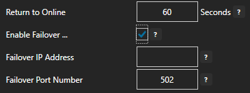
Modbus Failover
![]() To define a backup Modbus device enable the property Enable Failover under Configure-Drivers and set the IP Address and Port Number secondary device.
To define a backup Modbus device enable the property Enable Failover under Configure-Drivers and set the IP Address and Port Number secondary device.
If both the primary and secondary devices are offline the time to check for online status is Return to Online.
MTConnect Failover
![]() To define a backup MTConnect URL enable the property Enable Failover under Configure-Drivers and set the Live Data URL of the secondary data stream connection.
To define a backup MTConnect URL enable the property Enable Failover under Configure-Drivers and set the Live Data URL of the secondary data stream connection.
If both the primary and secondary streams are not reachable the time to check for online status is Return to Online.

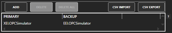
OPC DA Failover
![]() To define failover Classic OPC DA OPC Servers go to Configure-Options-OPC and define the list of primary OPC Servers and Backup OPC Servers.
To define failover Classic OPC DA OPC Servers go to Configure-Options-OPC and define the list of primary OPC Servers and Backup OPC Servers.
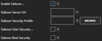
OPC UA Failover
![]() To define a backup OPC UA Server enable the property Enable Failover under Configure-Drivers and set the Server URL and Security Profile of the secondary server.
To define a backup OPC UA Server enable the property Enable Failover under Configure-Drivers and set the Server URL and Security Profile of the secondary server.
If both the primary and secondary servers are offline the time to check for online status is Return to Online.
Siemens S7 Failover
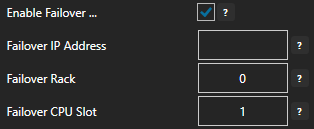
![]() To define a backup Siemens controller enable the property Enable Failover under Configure-Drivers and set the IP Address, Rack, and CPU Slot of the secondary controller that would have the same variable addresses as the primary controller.
To define a backup Siemens controller enable the property Enable Failover under Configure-Drivers and set the IP Address, Rack, and CPU Slot of the secondary controller that would have the same variable addresses as the primary controller.
If both the primary and secondary controllers are offline the time to check for online status is Return to Online.
Automatic Configuration with Dynamic User Interface
Open Automation Software offers OEMs full programmatic setup for their end users. This method greatly reduces the potential for human error in the setup process. Deployment of custom applications can be implemented from predefined scripts using SharePoint, Excel or a number of other methods. Time is saved both in deployment and in troubleshooting because of the decreased likelihood for error and the speed that you can deploy new and update existing projects.
The video below demonstrates how to use the Automated HMI Example that is included in the installation of Open Automation Software. The application automatically sets up data source configurations, trending, data logging and alarm limits. The HMI clients will adapt themselves automatically based upon what data source is defined.
.NET Programmatic Server Configuration
.NET Users can programmatically define all OAS configurations including tags and data logging as demonstrated in this video above. The OASConfig .NET Standard 2.0 assembly for .NET 5, .NET Core 2.o or greater, .NET Framework 4.61 or greater, Xamarin.iOS 10.14 or greater, Xamarin.Android 8.0 or greater, and UWP 1.0.0.16299 or greater or the OPCSystems assembly for .NET Framework 4.6 or less. The components are free to use and can be included in Windows Services, Web Services, ASP.NET or .NET MVC Web Applications, WinForm Applications, WPF Applications, and .NET Core Console applications. The assemblies can be used to communicate and setup local and remote services. Learn More…
REST API
The OAS Platform REST API allows developers to read and write real time Tag data, read real time and historical Alarms and Trends, and even create or update Tag configurations. It utilizes JSON data over HTTP(s) and can be used by any virtually any development platform or language. Learn More…
Getting Started – Node Red
OAS provides a simple and easily interface to move data between Allen Bradley, Siemens, Modbus, OPC UA/DA Servers, Databases, .Net applications and Node Red.
For a complete list of Data Sources and Data Destinations that the OAS MQTT Broker interfaces with, see the links below:
The video below is a complete tutorial on creating a Node Red Flow and Dashboard utilizing the OAS MQTT Broker:
- 0:00 – How to Integrate the OAS MQTT Broker with Node Red
- 0:52 – Node Red Dashboard installing instructions
- 1:14 – Network Section
- 1:22 – OAS as an MQTT Broker
- 2:44 – Add Debug Node to the flow and connect to OAS MQTT in node
- 3:05 – Standard JSON Format
- 3:15 – Separate the message out into individual values
- 5:16 – Level Displayed in Real Time
- 5:28 – Write Back to OAS
- 5:52 – Pull an MQTT out Node onto the flow to write back to OAS
- 6:18 – Dashboard Automatically Updates
- 6:22 – Pump Tag
- 7:09 – More Information
Step 1
Set up the OAS MQTT Broker: /data-destinations/mqtt-broker/mqtt-broker/.
Step 2
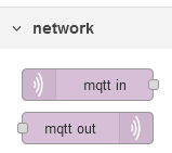
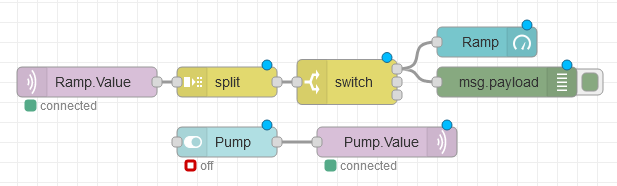
Open the Node Red Editor and start a new flow. To read data from the OAS MQTT broker pull an MQTT In icon out onto the flow. To write data to the MQTT Broker pull an MQTT Out icon out onto the flow.
Step 3
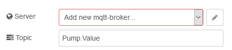
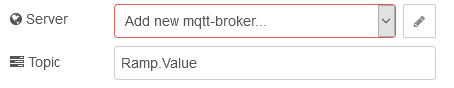
Double-click the MQTT In or MQTT Out node to bring up the properties window. Select Add new mqtt-broker from the Server dropdown and then click the pencil icon next to it.
In the server properties box, enter the OAS MQTT Broker Name and IP address. You can add a Client ID or leave it blank to auto generate an ID. Select Update when complete.

Step 4
You are now back to the MQTT Node.
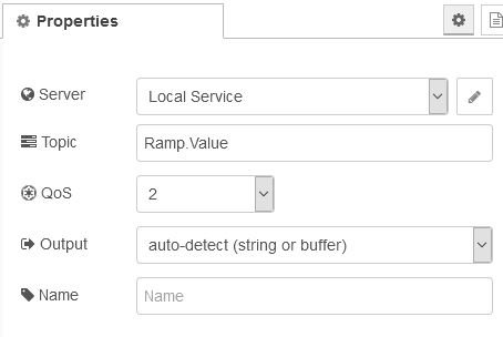
Select the server you created in Step 3.
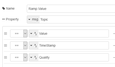
Enter an OAS Tag as the Topic and select a parsed JSON object as the output.
To access OAS tags set your topic to the OAS standard naming convention. A few examples below.
- Read the value from the Ramp tag on the local OAS service. Topic = Ramp.Value
- Read the Description from the Ramp tag on the local OAS Service. Topic = Ramp.Description
- Read the value of Alarms Not Acked tag in the subgroup Alarms on the local OAS service. Topic = Alarms.Active Not Acked.Value
Read the value of the Ramp tag from a remote OAS service. Topic = \Domain or IP address\Ramp.Value
\\192.168.0.1\Ramp.Value
Live Data Cloud Networking from local OAS Engine:
RemoteSCADAHosting.myLiveDataCloudNode.Ramp.Value
Live Data Cloud Networking through remote OAS Engine:
\\192.168.0.1\RemoteSCADAHosting.myLiveDataCloudNode.Ramp.Value
For more information on Tag naming conventions, please see the Tag Variables section of the Knowledge Base.
Step 5
OAS sends tag data in a standard JSON format that includes the value, time stamp and data quality.
A sample message is below.
Example Payload for Ramp.Value: {“Value”:84.0,”TimeStamp”:”2020-07-22T12:59:44-04:00″,”Quality”:true}
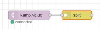
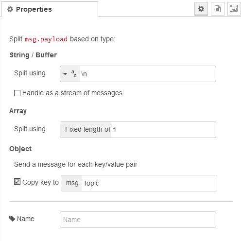
To segregate the payload in to separate messages add a split node to your project.
Check the Copy key to box and change it to msg.Topic as shown below.
Step 6
Now that you have separate messages add a switch node to access each message or the specific messages you want.
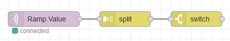
A complete Node Red Flow can be downloaded here.
Videos – MQTT Broker
OAS MQTT Client Connector
MQTT communication driver interface for interface with third party MQTT brokers.
OAS MQTT Broker
How to interface with the OAS MQTT Broker to connect to local and remote OAS tag values.

MQTT Client
How to connect to third party MQTT Brokers.
IoT Publish
How to publish data to Azure IoT Hub, AWS IoT Gateway, and MQTT Brokers.
Sparkplug B
Setup OAS as a Sparkplug B Edge of Network Node and also a Host Application.

- 00:00 – Introduction
- 01:10 – Download OAS
- 01:46 – Quick Start
- 02:08 – Edge of Network Node
- 05:52 – EoN Tags
- 07:04 – Host Application
- 09:20 – SpB Client Tags
- 10:22 – Programatic Interface
- 10:59 – CSV Export / Import
- 12:27 – Multiple Metric Tags
- 13:46 – Modbus
- 16:10 – DCMD Metric Write
- 17:00 – Data Route
- 17:58 – Networking
- 18:17 – Save Configuration
- 18:56 – OAS Platform