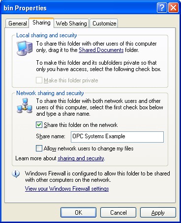
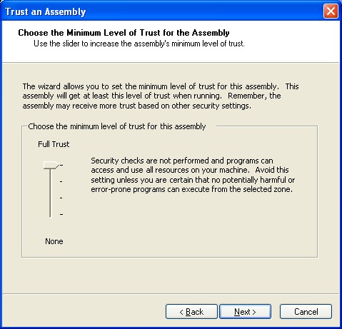
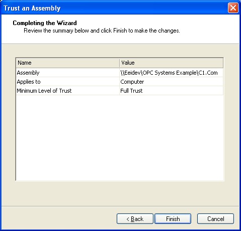
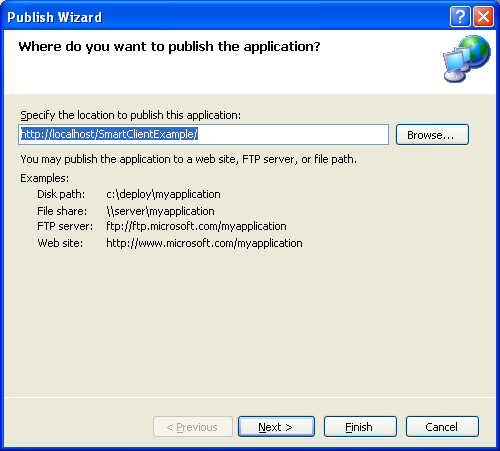
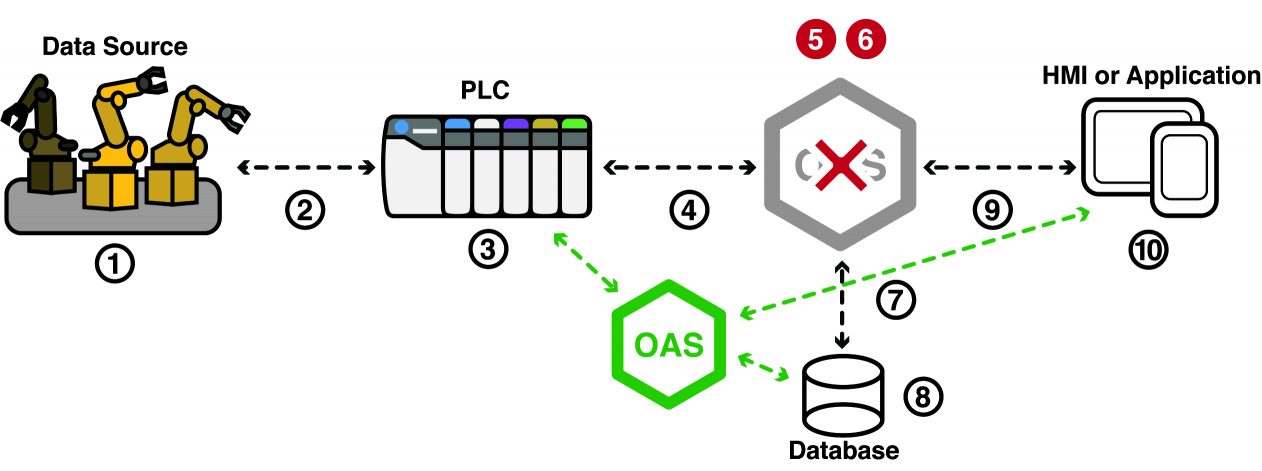
Open Automation Software Service Oriented Architecture supports any number of parallel servers and client systems. Following are some key attributes that help promote automatic switchover of one system to another. There multiple ways to implement redundancy for servers, data sources, databases, and applications.
Server – Redundancy
Use Same Tag Names On Parallel Servers
![]()
Open Automation Software real-time service can have the same group and tag name structure running on parallel servers. The source of the tags can be the same or different. For the most reliable connection to the data source it is best to run the OAS Services with direct connection to the source.
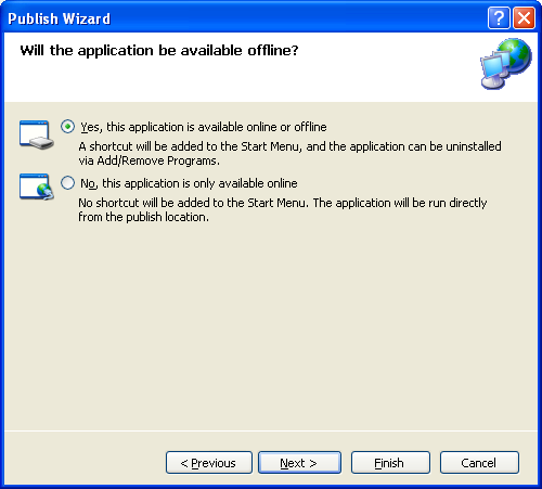
Client Application Switchover
![]()
Each .NET application can implement an automated or controlled switch to data servers.
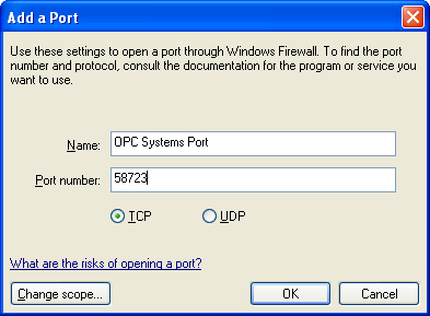
For automated client switch from primary server to backup server on either a server failure or tag quality failure use the AddBackupNetworkNode method to add monitoring of a primary server and backup server. If the tag values from the primary server are bad quality the backup server data will be used with the same tag name. Or if the entire primary server is unreachable the tag values from the backup server will be used. This provides redundancy for sensor failure, controller failure, communications failure to the controller, server failure, or communications failure to the server.
Example: AddBackupNetworkNode(“localhost”,”192.168.1.1”)
See Client Application Failover for more details and a video of demonstration of this feature.
For manual switchover the logic to determine which is the master can be variable based on quality of individual points. As an example if there are 3 redundant servers and each as a tag called DataQuality you can use logic to monitor the Qualities array from the event for each tag.
If all Qualities are True you can decide which server to the client should switch to. If only one of the servers is good quality then the choice is easy.
Use the AddNetworkNodeAlias method of the OASData.NetworkNodes, OPCSystemsDataConnector.NetworkNodes, OPCControls.OPCControlsNetworkNodes or OPCWPFDashboard.OPCWPFNetworkNodes components to alias the original network node definition of all tags defined to the network node to a different network node.
Example: AddNetworkNodeAlias(“localhost”,”192.168.1.1”)
The AddNetworkNodeAlias method is demonstrated in the Form FormMain of the WinForm Example Code.
Also demonstrated in the following WPF application in detail:
WPF Redundancy Client Example – Demonstrates automated switch to data servers:
Download the Redundancy Client Example
For all trend controls programmatically define the pens of the trend to remote nodes. An example is demonstrated in the Form FormMain of the WinForm Example Code.
For all alarm controls use the AlarmNetworkNodes property to define what remote services the alarm window is connected to. An example is demonstrated in the Form FormMain of the WinForm Example Code.
Visual Basic WinForm Example Code for realtime data access and all configurations access:
Download the WinForm VB Example
C# WinForm Example Code for realtime data access and all configurations access:
Download the WinForm C# Example
Create Master Tag in Each Service
![]()
In Open Automation Software create one or more tags to provide a status of it being a master is active mode or standby mode. These tags can be used by client applications for determine switchover logic and also for activate properties in data logging, alarm logging, alarm notification, report, and recipe configurations.
The data source for the tag can be a Calculation to automatically monitory other service tags with the Quality parameter or the value can be set from other remote applications like a .NET application, Microsoft Excel, OPC Clients, OPC Servers, or databases.
It best to include a heartbeat within a Calculation tag to verify that the remote service or application is still communicating to the service.
The logic to determine if a service is completely variable, but do not implement something that will prematurely put the service in a standby mode leaving no service as the master.
Things to consider if a service should be the master:
- Network failure
- PLC / controller communications failure
- OPC Server failure
- OPC Server communications to devices (PLCs)
- Database engine access
- Remote service shutdown or PC failure
Source When Bad to Different Remote Tag
![]()
For each Tag value there is a Source When Bad property that can be set to another local or remote Tag when the data quality of the original source is bad. The Source When Bad property can be set to Set Sources To Tag Value and then alternate source can then be defined to another Tag.
Enable Communications from Tag
![]()
Communications to a data source can be enabled or disabled with the property Enable by Tag.
When the Enable by Tag property is enabled a Boolean Tag can be defined to enable of disable the communications based on its value.
Retain Values, Alarm Limits, Times, Trends, Alarms
![]()
Under Configure-Options-Retain Values you can enable to store to disk the following information so when the service computer is restarted all of the latest values are retained.
Values and Alarm Limits for any Tag Value or Alarm Limit with a data source of Value.
Time and Counts for keeping track of times and counts for individual tag parameters with the feature Time On and Counts enabled.
Trends for real-time trend cache.
Alarms for all real-time alarms and the ability to retain when the alarm originally occurred.
File Data Source for Redundant Servers
![]()
To share values and alarm limits across multiple servers the Data Source of a Tag Value or Alarm Limit can be set to File Binary, File Text, or File XML. The path of the file that is shared is specified under Configure-Options-File Data Source.
This path can be set to a remote drive and directory that is accessible by all redundant services. For all tag names that are the same on each service with the Data Source of File all will be updated with the same value when one of the services receive a write from a client.
It does require that the remote file be able to be accessed in order to update the tag value on the multiple services.
Data Source – Redundancy
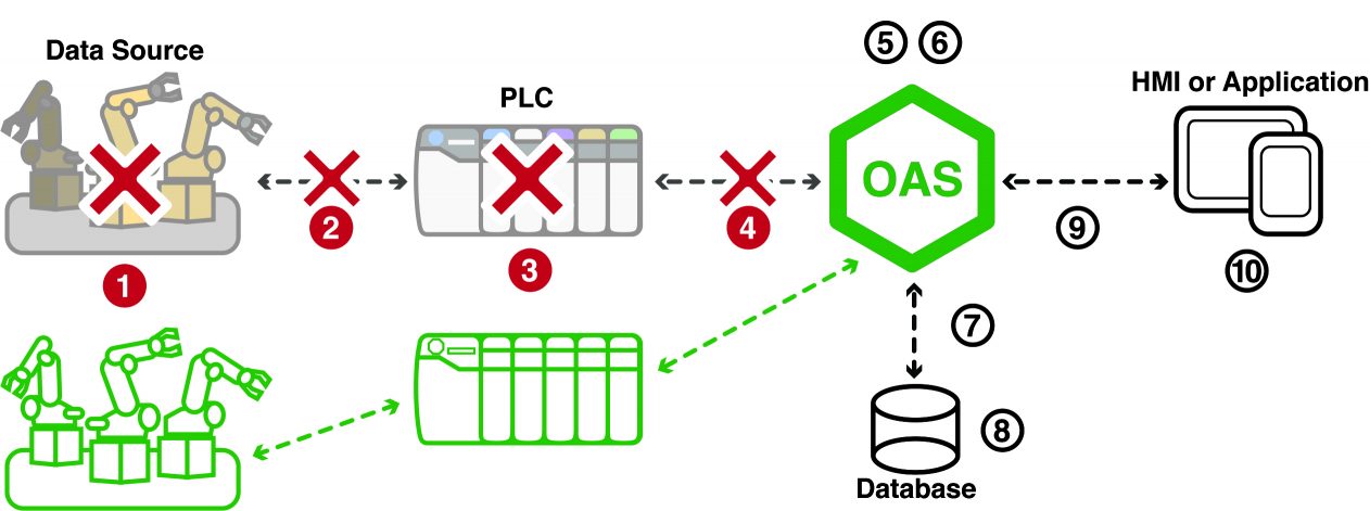
Driver Interface Failover
![]()
Each Interface can optionally enable a failover connection if the primary connection fails. To enable the failover option use the driver interface property Enable Failover. This can be set for AB Classic, AB Logix, AWS IoT Gateway, Azure IoT, CANBus, Modbus, MQTT, MTConnect, OPC UA, and Siemens.
To define failover Classic OPC DA OPC Servers go to Configure-Options-OPC and define the list of primary OPC Servers and Backup OPC Servers.
See Driver Interface Failover – Communication Redundancy for detailed instructions for setup.
AddBackupNetworkNode for .NET applications is also applicable to resolve a data source failure.
Activate Properties
![]()
Each configuration in Open Automation Software including data logging, alarm logging, alarm notification, reports, and recipes all have an Activate by Tag property under the Common tab of each configuration group to enable or disable the groups execution.
This can be assigned to a Boolean master tag that is true when the features should be enabled and false when disabled. You may need to use additional Calculation tags for each group if more than just an active master tag determines if the execution state of the configuration group.
Database – Redundancy
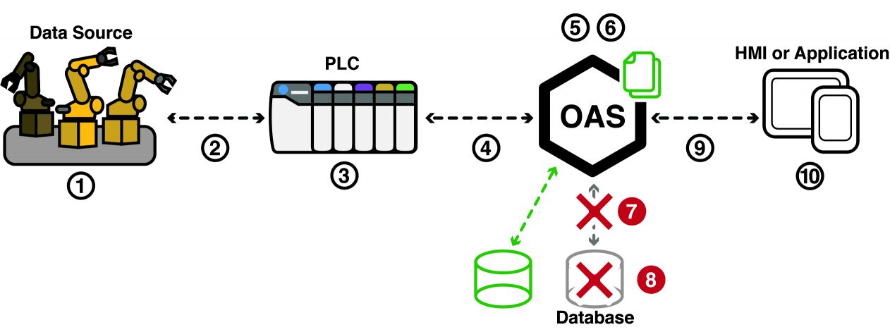
Data Buffering For Logging, Trending, and Alarms
![]()
Each service runs as a Windows Service and on network failure to remote clients all data is retained locally in the service. All trend, alarm, and data logging data is cached in the service at all times to be available for remote clients.
When performing data logging of data from a remote service data can be written to the local hard disk using the Data Buffering feature found under Configure-Options. The same is true for a database engine failure or a network loss to a remote database engine.
View the following video on data buffering to disk.
Data Buffering
How to setup data logging so there is no data loss on a network or database engine failure.
Data Log-Override All Data Logging Server Names
![]()
The same data logging configuration can be used on multiple services. If each service needs to log to a different database engine the property Override All Data Logging Database Server Names can be used to override all server names in all logging groups to point to only that database engine server.
Error Feedback in Data Logging Groups
![]()
Each data logging group has a property to enable a write of status to an Integer tag. The definition of each error code and assignment of error feedback tag is found under the Common tab of each data logging group.
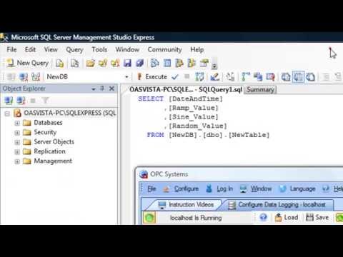
Log to the Same Table from Multiple Servers
![]()
The OAS Engine data logging and alarm logging groups can be enabled and disabled based on tag values. You can have as many logging groups on the same server or multiple servers which can automatically activate based on tag value or quality.
See Redundant Data Logging to the Same Table from Multiple Services for details of setup.
Application – Redundancy
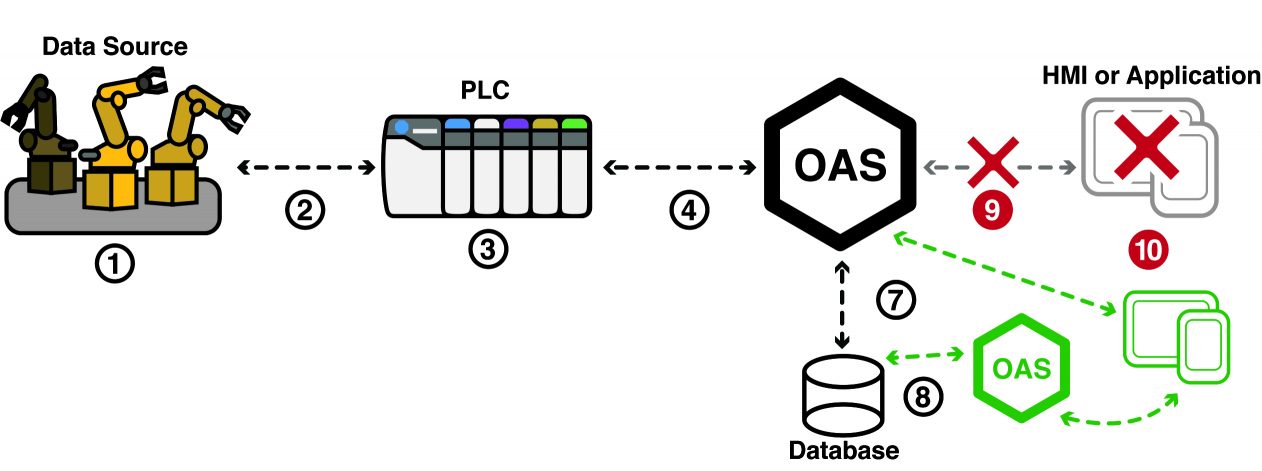
Each OAS service can support multiple client applications to monitor same or dissimilar tag lists. Data quality and timestamp is delivered from the data source to the final use of the data. If logging data or alarms to a database multiple OAS services can receive data from remote OAS services to log to the same or different database engines.
See Client Application Failover for automated switch from primary server to backup server when an application looses communications to a server or the tag quality from the data source is bad.