Your OAS Engine service (the Windows or Linux service) will typically always be running unless you need to refresh the OAS instance to reboot your server or troubleshoot OAS. All of the current configuration is stored in memory and can be managed using either the Configure OAS application or one of the configuration APIs. As long as the OAS Engine service is running, you can make changes to the configuration irrespective of whether OAS is in the Running or Stopped state.
You can start and stop the OAS runtime without stopping the overall OAS Engine service. When the runtime is stopped OAS will not connect to any device and will not process any data. You can learn more about this in Local and Remote Configuration section of the Overview – Configure OAS page.
If OAS is in the Running state any configuration changes will apply immediately. You will need to stop the runtime if you want to load a configuration file, but note that this will stop OAS from processing and communicating.
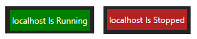
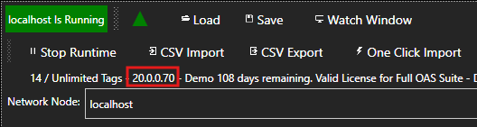
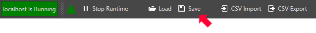
In Configure OAS you will see the runtime state in two possible states. The hostname of IP address of the instance you are connected to will be shown.
⚠️
You will not lose your configuration if you start or stop the OAS Runtime. However, if you stop the OAS Engine
Windows/Linux service, then any unsaved configuration will be lost.
Default Configuration Files
When the OAS Engine service is started it will automatically load the configuration from a set of files as configured in the Options > Default Files screen. These are known as the Default Configuration Files. Configurations for each screen are stored in independent configuration files.
💡
The Tags and Drivers screen share the same configuration file.
By selecting the configuration and providing a file path, you are telling OAS which types of configurations and which corresponding file you want to load when the OAS Engine service is started. Any configurations that are not specified will start with an empty configuration.
⚠️
It is important to understand that changing the OAS configuration will immediately update the OAS instance that
is running, but to ensure that changes are not lost when the OAS Engine service is restarted, the configuration
needs to be saved to file and set in the Default Files screen
Saving Configuration
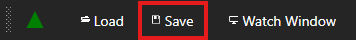
You can save the configuration at any time as long as you are connected to a local or remote OAS Engine. This can be done using the Save button on any of the Configure OAS screens where saving is supported.
Each screen will save the configuration to a file with a different file extension.
Some screens do not have a Save button as any changes are saved immediately. The following screens are saved automatically:
Options
Security
Users
License
To save a configuration, click on the Save button.
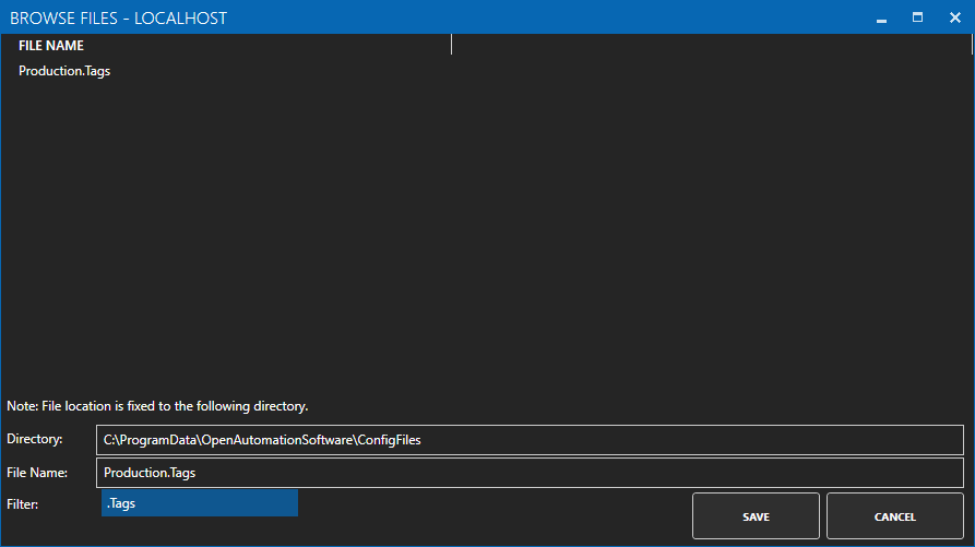
In the dialog window provide a File Name. The file extension will be automatically set for each screen. Click on the Save button.
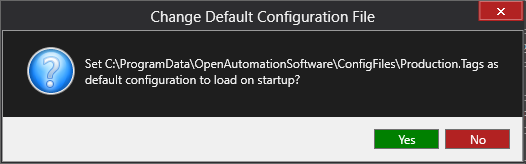
If this is a new file name, it will ask you if you want to make this the default file so that your configuration is loaded when the OAS Engine service is started.
If you click Yes the corresponding default file setting in the Configure > Options > Default Files tab will be automatically updated. For example, if you updated the Tags screen you will now see something like this.
Your Tags configuration will now be loaded from this file whenever the OAS Engine service is started.
💡
Windows: Configuration files will always be stored in the C:\ProgramData\OpenAutomationSoftware\ConfigFiles folder.
💡
Linux: Configuration files will always be stored in a ConfigFiles sub-folder of the OAS installation directory.
Loading Configuration
You can manually load a configuration file using Configure OAS or one of the OAS APIs.
⚠️
If you are loading Tags or Drivers configuration via the Tags file you will have to stop the OAS Runtime. Stopping the Runtime will stop any data processing and communications.
If you are loading a Tags configuration file, you will first need to stop OAS Runtime. Otherwise continue to step 2. Click on the Stop Runtime button to stop the runtime.
Click on the Load button.
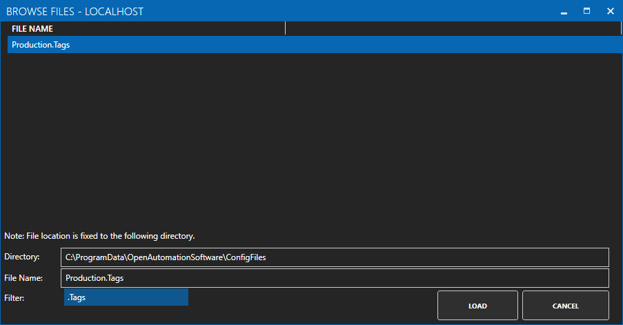
Select the configuration file that you want to load. It will automatically show only the configuration files with the correct file name extension that matches the screen you are currently configuring.
If your OAS Runtime was stopped, start the runtime by clicking on Start Runtime. OAS will then start communications and process data.
💡
In a typical production environment you will have your configuration files defined in the Configure > Options > Default Files screen so that when the OAS Engine service is started due to a server reboot or is re-started after an updated, the configuration files will be automatically loaded.
Configuration APIs
You can save and load OAS configuration using the OAS configuration APIs.
If you have already installed OAS you can update your system using the Manual or Automatic update method.
⚠️ You should take care not to delete the installation director or the Config directory containing your options, security and license data. These files can remain and your OAS product will remain activated.
In Windows, the configuration files are located in: C:\ProgramData\OpenAutomationSoftware\ConfigFiles,
In Linux, the configuration files are located in the Config directory of your OAS installation path.
Automatic Update
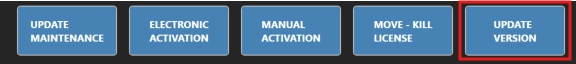
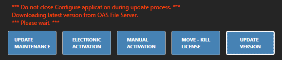
To upgrade an existing system open the Configure OAS application using “Run as Administrator: mode and then select the Configure > License menu and click on the Update Version button.
It is recommended that you first save your changes. It is also recommended to close all Internet Browser applications if you are using UIEngine.
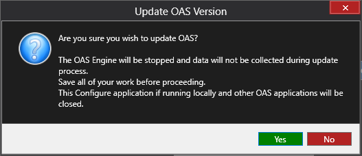
⚠️ Note that the OAS Engine will be stopped during the update process.
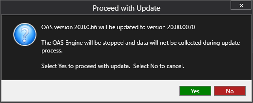
The installation process will first confirm the version number and request your confirmation. Click Yes to proceed.
Do not close the Configure OAS application. A message will be displayed during download and installation. The Configure OAS application will close automatically.
You can verify your software version on any screen in the Configure OAS application.
Manual Update
First download the OAS Platform.
For Windows uninstall Open Automation Software in the Programs and Features settings menu of your Windows operating system. Once uninstalled run the new setup and start the OAS Services.
For Linux simply copy in the extracted files to the OAS Engine directory.
The Tags configuration screen in the Configure OAS application provides the following high level features:
Create, update and delete Tags and Tag Groups
View latest tag value, timestamp and quality
Write to a tag value
Configure tag alarm limits
Configure data route target
Configure tag Sparkplug B parameters
Advanced alarm acknowledgement and scheduling
Turn on tag statistics (Time On and Count and Tag Totals)
👉 To learn about Tag Groups and Tags check out the Tags Overview page 🔗
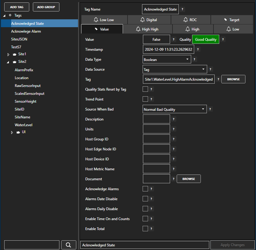
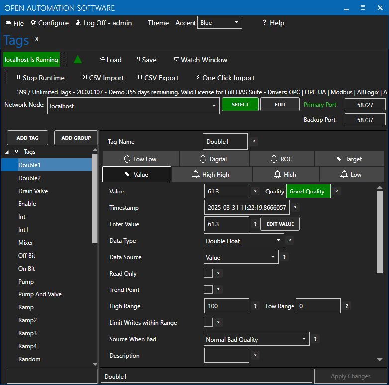
The Tags configuration screen lists all Tag Groups and Tags on the left hand tree menu. The main right hand side allows you to configure the Tag’s parameters.
Tag Groups and Tags List
The left hand side panel lists all of your tag groups and tags in a hierarchical tree menu. You can think of Tag Groups as folders and Tags are like files in a folder. You can organize your Tags into logical groups and design the data model that best fits the solution you are trying to create.
Tag Groups
The Tags Tag Group is the base or root Tag Group. You cannot delete or rename this Tag Group.
Add Tag Group
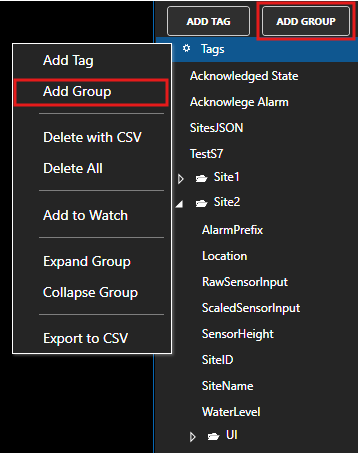
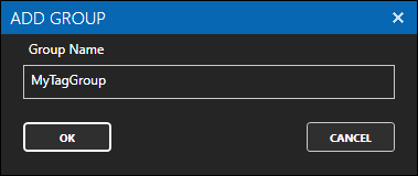
To add a Tag Group first select the root Tag Group or the Tag Group where you want to add a Tag Group. This will be the parent Tag Group or the new Tag Group. Either click on the ADD GROUP button or right click on the parent Tag Group and select Add Group. Provide a name in the dialog window that appears. The Tag Group name has to be unique within the parent Tag Group.
Delete Tag Group
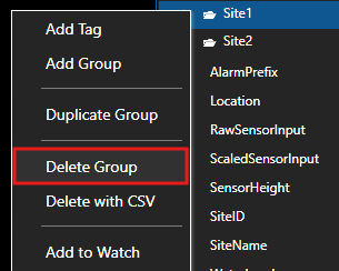
To delete a Tag Group first select the Tag Group you want to delete. Make sure it is highlighted. Right click on the Tag Group name and select Delete Group or use the Delete key on your keyboard. Click Yes in the confirmation dialog to delete the Tag Group.
Rename/Duplicate Tag Group
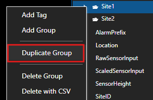
To rename a Tag Group you can use the Duplicate function. This will create a new Tag Group with the new name and same Tag structure. The duplicate Tag Group will be created at the same level in the hierarchy as the Tag Group being copied.
You can also use this to copy an existing Tag structure and create a new copy of it. This is useful when you have a particular data model and you want to re-use the same Tag structure in a new copy.
Tags
Tags are contained in Tag Groups. You can organize your Tags into as many different Tag Groups as you want, including in the root Tag Group, to create an appropriate representation of your data or process.
Add Tag
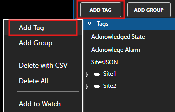
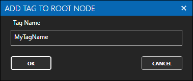
To add a Tag select the Tag Group in which you want to create the Tag. This can also be the root Tags Tag Group. It is often best to first create your Tag Group structure. Once your Tag Group is selected, either click on the ADD TAG button or right click on the Tag Group and select Add Tag from the context menu. Provide a name in the dialog window that appears.
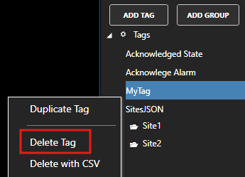
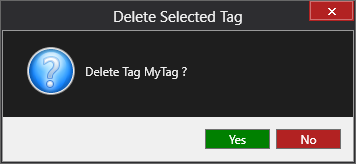
Delete Tag
To delete a Tag first select the Tag Group you want to delete. Make sure it is highlighted. Right click on the Tag Group name and select Delete Group or use the Delete key on your keyboard. Click Yes in the confirmation dialog to delete the Tag Group.
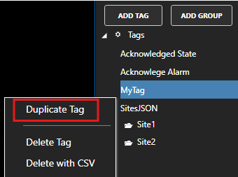
Duplicate Tag
To duplicate a Tag you can use the Duplicate function. This will create a new Tag with a new name and copy all of the properties from the original Tag. The duplicate Tag will be created in the same Tag Group as the original Tag.
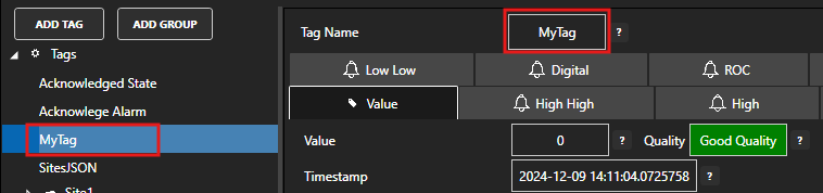
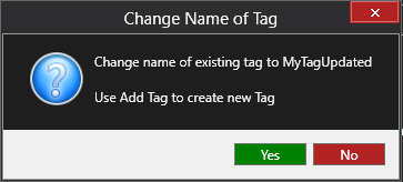
Rename Tag
To rename a Tag first select the Tag and make sure it is highlighted. Edit the Tag name in the Tag Name field and then click on the Apply Changes button or press the Enter key on your keyboard. Click Yes in the dialog window to confirm the update.
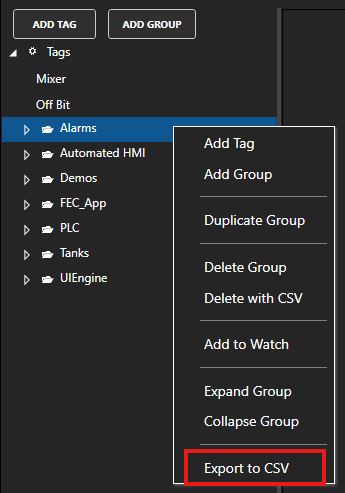
Tag Group Export to CSV
Instead of exporting all of your tags, you can choose to only export tags in a particular Tag Group. This will include all descendant Tags in the selected Tag Group hierarchy.
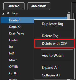
Delete with CSV
If you need to delete a large number of tags, you can use the Delete with CSV feature. The standard CSV Import feature can only insert and update data.
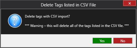
Select the root Tags item or select any Tag or Tag Group and click on Delete with CSV.
In the confirmation dialog click Yes to confirm that you want to delete tags using CSV delete.
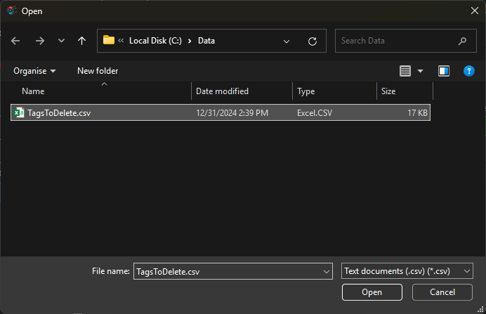
Select a CSV or text file where the first row contains at least one column called Tag and the tag path on each subsequent row.
A quick method to create this file is to use the Export to CSV functionality and in the CSV Column Selection dialog deselect all of the items. This will result in a CSV file that only contains the tag name. You can then use Excel to remove any tags you want to keep so that only the tags you want to delete remain.
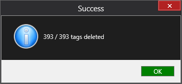
Once the tags have been removed you will see a confirmation dialog window.
💡
This feature will only delete the Tags and not the Tag Groups, so you’ll have to manually delete the Tag Groups. The alternative is to export all of your Tags, keep only the tags that you want to keep, use the Delete All menu to remove all tags and then use CSV Import to load only the tags you want.
The Configure OAS application is the primary configuration tool for configuring the OAS platform. It can be used to configure both locally installed and remote OAS instances as long as the remote instance is reachable via a network from the host where Configure OAS is used.
If you are using the Windows version of the OAS platform, the Configure OAS application is included by default.
If you are running on a Linux platform, you will find the download link for the Configure OAS application in the Downloads section. The Linux version has been tested on:
Ubuntu
Linux Mint Cinnamon
Linux Mint XFCE
Linux Mint Mate
Debian KDE
You can use Windows or Linux to configure any any local or remote OAS instance running on Windows or Linux, as well as Docker or Raspberry Pi.
In this guide you will learn about the Configure OAS application’s main features and screens.
Windows Installation
Configure OAS is installed by default when you install the OAS platform on a Windows host.
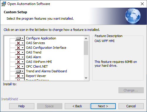
You can also install the Configure OAS application without installing the main OAS services. This can be useful if you have a configuration or maintenance server that users will use to configure remote OAS instances. This is especially useful if you have Linux or Docker installations and you need to configure them using Configure OAS. To achieve this, make sure you select a Custom installation type when installing OAS.
In this example we will only install the Configure OAS application and the Trend and Alarms Dashboard. Both of these applications can connect to remote OAS instances.
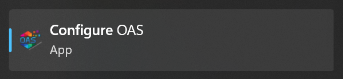
The Configure OAS application can be started from the Windows start menu. You can find it there by searching for Configure OAS or by locating it in the Open Automation Software start menu folder. The icon will look similar to this example.
Linux Installation
You can install the Configure OAS application on a Linux machine independently to the main OAS platform. Once you have downloaded the relevant Debian installer you can run your installation using the following command.
sudo dpkg -i oasconfiguration_linux-amd64.deb
Once installed you can run the application using the oasconfiguration command or using the Configure OAS shortcut in the start menu.
Local and Remote Configuration
Because the Configure OAS application is a stand-alone application, it can be used to configure any running OAS instance that can be reached either locally on the same host or on the network where the Configure OAS application is installed. If you are connected to the internet, it can even access any publicly accessible OAS instance host as long as you have the IP address or the host name and the OAS services are exposed.
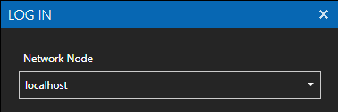
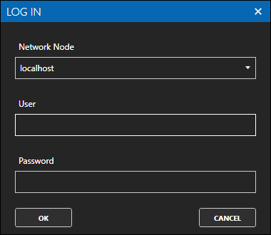
During login and within the OAS instance you have the option to select the Network Node that you want to connect to. The term Network Node simply means the IP or hostname of the local or remote OAS instance that you wish to configure.
In the login dialog window you can provide a Network Node:
When you open a configuration screen, you can also set the Network Node you want to access:
Note that once you login, those credentials will be used for all configuration actions with an OAS instance. This assumes that you have the same username and password configuration on all your network nodes, otherwise you’ll have to login with different credentials and then update the network node.
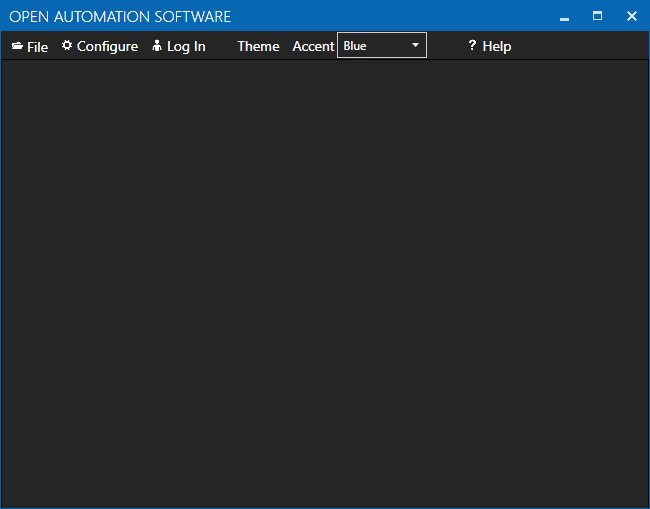
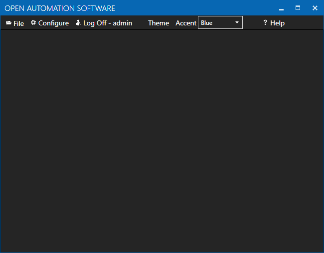
Main Window
When you launch the Configure OAS application you will see a toolbar and a blank surface below this.
Logged Out State
By default, the Configure OAS application is in a logged out state with no configuration screens open.
Here is an overview of the menu items:
Menu Item
Description
File
Use the File > Exit menu item to close the application.
Configure
Access to the configuration screens.
Log In
Login as an authenticated user.
Theme
Select a light or dark theme.
Accent
Select the theme accent.
Help
Access further help and resources.
Login
When you access a configuration screen in the Configure menu, Configure OAS will ask you to login. If you have installed OAS for the first time you will be asked to set up a new Admin account password. This will give you full access to Configure OAS. If you are logging in to an existing OAS instance you can use whichever user accounts you have configured for the instance you are configuring. This will depend on your security configuration.
If you have security configured where the Default security group has been restricted and you cancel the login, the configuration screen will still load, but you will see error messages.
Logged In State
After you login, you will see the username that you used to login appear in the toolbar and the Log In menu item will now say Log Off.
Configuration Screens
The Configure OAS configuration screens allow you to configure all of the various OAS platform features. You can access each screen by selecting the screen name from the Configure menu. This menu is organized by OAS features.
Here is a list of available screens and associated Knowledge Base links to help you find more specific information:
You can use this setting to automatically clear and acknowledge Hi and Lo alarms if a HiHi or LoLo alarm occurs respectively. These two set-points are independent so you can use either one or both together. However, note that a Lo or LoLo cannot be cleared by a Hi or HiHi and vice versa.
If you have a Lo and a LoLo alarm threshold configured, then the Lo alarm will be cleared and acknowledged once a LoLo alarm occurs.
Similarly, if you have a Hi and a HiHi alarm threshold configured, then the Hi alarm will be cleared and acknowledged once a HiHi alarm occurs.
You can use all four setpoints if you like, the only thing to note is that if a LoLo occurs and after some time a Hi and then a HiHi occurs, the LoLo will not clear automatically. Similarly, if a HiHi occurs and after some time a Lo and then a LoLo occurs, the HiHi will not clear automatically.
This setting allows you to escalate your alarms without polluting the alarm screen with both alarm setpoints.
Default: Disabled
Keep Alarms when Disabled and Normal and Not Acknowledged
When this setting is disabled, an active alarm will be cleared and acknowledged if the alarm setpoint is disabled.
When this setting is enabled, an active alarm will be cleared, but not acknowledged if the alarm setpoint is disabled.
You can use this to ensure any active alarms cannot vanish from your alarm visualisations if the alarm is disabled for whatever reason. For example, you might disable alarms when you do maintenance to prevent any new alarms, but you don’t want to automatically acknowledge any alarms that were already active.
Default: Disabled
Update Alarm Status Immediately without Alarm Time Delay
Every Tag has a boolean AlarmActive property for each alarm threshold type to indicate whether the alarm is active or not. If the relevant AlarmActive parameter is True it means that the alarm is active.
The following alarm status parameters are available:
HighHighAlarmActive
HighAlarmActive
LowAlarmActive
LowLowAlarmActive
DigitalAlarmActive
ROCAlarmActive
When this setting is disabled, the relevant AlarmActive property will only become True once the alarm delay has expired.
When this setting is enabled, the relevant AlarmActive property will become True as soon as the alarm threshold is met.
This setting is useful if you want to know if an alarm threshold has been met irrespective of the delay or if are using calculation tags where you want to know if a particular alarm setpoint has been reached so you can immediately trigger another condition.
Default: Enabled
Set Alarm Date and Time with Time Delay
This setting relates to the alarm timestamp of real-time alarms and whether it includes the alarm delay or not. This impacts alarm timestamps in real-time alarm data tables, alarm visualizations and alarm logging history.
When this setting is disabled, the alarm timestamp is set to the timestamp of when an alarm limit is reached and does not include the delay.
When this setting is enabled, the alarm timestamp is set to the timestamp of when the alarm limit is reached and the alarm delay expires.
Default: Disabled
Retain All Realtime Alarms to Show All Occurrences in Window
When this setting is disabled each instance of an alarm for a particular tag alarm limit will replace the previous alarm instance if it is still unacknowledged.
Let’s say you have a Digital alarm limit configured on one of your tags. When this alarm occurs, the alarm will be displayed on the alarm screen. Once it clears it will be shown as cleared and unacknowledged. When this alarm occurs again, OAS will remove the previous alarm from the real-time alarms and display the new alarm instead. The old alarm will remain unacknowledged in the database if you have alarm logging enabled.
With this setting disabled only the most recent alarm instance will be shown. In terms of alarm logging, it will still log each alarm instance assuming you have the relevant filters configured.
When this setting is enabled each alarm instance will be retained in the real-time alarm screen.
Let’s say you have a Digital alarm limit configured on one of your tags. When this alarm occurs, the alarm will be displayed on the alarm screen. Once it clears it will be shown as cleared and unacknowledged. When this alarm occurs again, a second alarm instance will be added to the real-time alarms. Previous alarms will only be removed from the screen if you acknowledge the alarm (and your alarm filters are not configured to show inactive and acknowledged alarms.)
This setting allows you to display every instance of an alarm to your operators rather than just the most recent instance. This is an important feature if you require all alarm instances to be acknowledged even if already cleared.
Note that since alarms will never be removed from the real-time alarms table you will need to make sure your OAS host has sufficient memory to deal with the number of expected alarms over time. It is a good idea to use the Remove Old Alarms from Realtime Alarms option to automatically clean out old alarms based on an expiration time.
Default: Disabled
Remove Old Alarms from Realtime Alarms
Removes cleared and acknowledged alarms from real-time alarms when the alarm date and time is older than the given number of hours.
This setting is used together with the Retain All Realtime Alarms to Show All Occurrences in Window feature to ensure memory consumption does not grow beyond a manageable amount.
⚠️ Warning: This feature will remove alarms older than the configured number of hours irrespective of the state, including active and unacknowledged alarms.
Default: 0 hours
Delay Alarm Logging and Notification on Startup
When enabled, this feature ignores alarm limits when OAS first enters runtime mode until the given number seconds elapses.
This setting is useful for allowing your system to reach a steady state before monitoring your alarm limits. This can be useful for things like taking into account device first time connection delays, waiting for external services to start and waiting for the first data poll.
Default: 0 seconds
Remove Carriage Return and Line Feed from Alarm Text
Each Tag alarm limit has the option to create alarm text from dynamic sources. In cases where the alarm text contains carriage return or line feed characters, for example due to the constraints of an external system, this feature can be enabled to remove those characters and ensure your alarm screen and text is not impacted.
Default: Disabled
Enable Writes as Operator Events
This setting can be used to create a log of all write events performed by operators in OAS UI Engine, Windows Forms, WPF and Web controls using the real-time and alarm logging features. When this setting is enabled, any writes to a Tag value will be logged in real-time alarms as an Operator Event alarm type and group.
The operator’s username and the value written will also be logged.
This setting is useful for change auditing. You can use alarm logging with alarm filters to only log Operator Event alarms to keep the operator events separate from normal alarm logging.
Default: Disabled
Remove Cleared Alarms with Comment Containing
This setting allows you to remove an alarm from the real-time alarm screen when a comment is added and the comment contains the string configured in this setting. A comment can be added whilst the alarm still still active, but the alarm will only be removed once the alarm clears.
It is important to note that the alarm will be removed from the real-time alarms, but no acknowledgement state or timestamp will be logged in the alarm history.
Default: Empty string
Redundant Remote Services to Ack Alarms
This setting allows you to specify the alarms that will be acknowledged on a remote redundant OAS instance when alarm are acknowledged on the instance you are configuring. This is useful when you have more than one OAS instance acting as a redundant instance and when an alarm is acknowledged on a primary instance, your redundant instances will also acknowledge the alarm.
This setting is configured by specifying all of the host names or IP addresses of the remote OAS instances where you want alarms to be acknowledged.
Default: Empty list
Common
CSV Export Delimiter
This setting allows you to specify the delimiter that is used when exporting or importing configuration data using CSV files in the Configure OAS application or using an API call.
Default: ,
Array Delimiter
This setting allows you to specify the delimiter that is used when parsing arrays from string values.
Default: ,
Data Log
Override All Data Log Servers
This setting is a global override for the data logging host name or IP address for all data logging groups. When enabled, the server host or IP address specified in the Database Server Name setting will be used for all data logging groups.
Default: Disabled
Database Server Name
This setting defines the server host or IP address for the Override All Data Log Servers setting.
This setting is only visible if the Override All Data Log Servers setting is enabled.
Default: localhost
Maximum Connections / Database
This is the maximum number of Database connections that data logging will use for data logging groups that are using the same database server and authentication. For example, with a value of 10 if there are 30 data logging groups that are all using the same database engine and authentication for a connection, there will be 10 connections made to the database engine with 3 logging groups assigned to each connection.
Default: 10
Data Route
Allow Write to Bad Quality Targets
When disabled writes will not occur to tags with bad data quality. Required for MQTT, Sparkplug B, and AWS.
Default: Enabled
Include Quality with Writes to OPC
Include the OPC Quality in writes to Classic OPC Servers.
Default: Disabled
Write Frequency When Bad Quality
he frequency to write values when the destination data quality is bad.
Default: 10 seconds
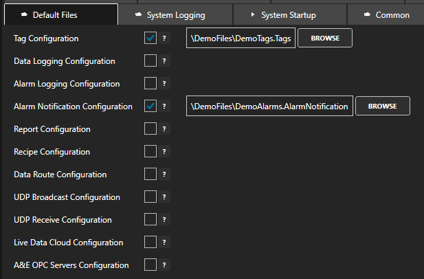
Default Files
OAS configuration data is distributed across a number of different files depending on the feature being configured. The Default Files screen allows you to enable or disable automatic loading of configuration files when the OAS service is started. Each feature configuration file path can be independently configured.
Configuration files can only be loaded from a fixed configuration folder. On Windows, it is the C:\ProgramData\OpenAutomationSoftware\ConfigFiles directory. On Linux, default configuration files must be stored in the ConfigFiles folder relative to the OAS installation.
The following default configuration file paths can be specified:
Tag Configuration
Data Logging Configuration
Alarm Logging Configuration
Alarm Notification Configuration
Report Configuration
Data Route Configuration
UDP Broadcast Configuration
UDP Receive Configuration
Live Data Cloud Configuration
A&E OPC Servers Configuration
Default: Tag Configuration – “\DemoFiles\DemoTags.Tags” Alarm Notification Configuration – “\DemoFiles\DemoAlarms.AlarmNotification”
Drivers
Use TimeStamp from Controllers
This setting controls whether to use the timestamp provided by Allen Bradley and Siemens controllers when reading tag values or whether to use the OAS host time.
When this setting is enabled, OAS will use the timestamp provided by the controller when updating a Tag value.
When this setting disabled, OAS will use the current date/time of the host machine.
Default: Enabled
Maximum Driver Threads
This setting defines the maximum number of threads that OAS can use for driver interfaces. This value will depend on available system resources.
Default: 100
Reset Interface on Channel Error
Reset the driver interface on a channel failure when the Driver type is AB Logix, AB Classic, or Siemens.
Default: Disabled
Reset Interface on Device Error
Reset the driver interface on a device failure when the Driver type is AB Logix, AB Classic, or Siemens.
Default: Disabled
Retry Connection Time After Error
The time delay after a channel or device error for AB Logix AB Classic and Siemens.
Default: 60 seconds
Siemens Optimized Polling
Can be disabled to isolate invalid addresses in Siemens Tags. Leave enabled for fastest performance in production.
Default: Enabled
File Data Source
Alarm Group for Errors
The Alarm Group to assign to alarm instances for errors when an error occurs with saving or loading a value to the file.
Default: FileDataSource
History
Enable History Date Format
This property is required when the database engine language is set to something different than the operating system regional language setting.
When enabled, the date time format must be specified. The default format is “yyyy-MM-dd HH:mm:ss”.
Default: Disabled
Maximum Web Alarm Records
The maximum number of alarm history records to return to a web client request.
Default: 100
Live Data Cloud
Disable Live Data Cloud
This property will restrict what remote OAS Engines can self host through this service. When enabled only the specific Live Data Cloud nodes that are added to the Allowed List will be able to self host through this service.
Default: Disabled
MQTT Broker
OAS MQTT Broker ID
The ID of the OAS MQTT broker.
Default: OAS
OAS MQTT Broker Port
This setting defines the port on which the MQTT broker will listen for connections that do not use encrypted connections.
Default: 1883
OAS MQTT Broker SSL Port
This setting defines the port on which the MQTT broker will listen for connections that use encrypted connections.
When this setting is enabled, the OAS MQTT Broker Enable SSL setting should be used to specify the SSL configuration.
Default: 8883
OAS MQTT Broker Enable SSL
Enable encryption over SSL using the private key specified in the MQTT Private Key File setting and the private key password specified in the MQTT Private Key Password setting.
Default: Disabled
MQTT Private Key File
This setting is only visible if OAS MQTT Broker Enable SSL is enabled.
Default: Empty string
MQTT Private Key Password
This setting is only visible if OAS MQTT Broker Enable SSL is enabled.
Default: Empty string
MQTT Client Username
The username for the OAS MQTT broker.
Default: Empty string
MQTT Client Password
The password for the OAS MQTT broker.
Default: Empty string
Topic Aliases
Provides a way to map topic names to a tag names. Only required if the MQTT client cannot adjust topic names to match tag names.
Default: Empty list
Networking
Primary Port Number
The primary TCP port number that is used for service to service communications and client to service communications for this service.
Default: 58727
Backup Port Number
The backup TCP port number that is used for service to service communications and client to service communications for this service.
Default: 58737
Enable Classic TCP (Unsecure)
Enable this property if the remote services or applications are using the classic OAS TCP interface.
Default: Disabled
OAS OPC UA Server Port
The port number that is used for the Open Automation Software OPC UA Server.
Default: 58728
REST API and Web Port Number
The port number that is used for REST API and Web interfaces.
Default: 58725
REST API and Web Use SSL
Use SSL for REST API and Web interfaces.
Default: Disabled
REST API and Web Certificate ID
The Certificate ID for REST API and Web interfaces when the service is running on Windows OS.
Default: None
Client Packet Rate
The communication rate between the service and remote services and client applications. Use a faster rate if you want to have faster communications.
Use the default of 100 ms if there are more than 100 client applications connecting to the service.
Use 1,000 ms if there are more than 1,000 client applications communicating to this service.
Default: 30 milliseconds
Websocket Update Rate
The maximum communications speed from the UI Engine. Set to a value of 0 to allow all tag values with no restriction.
Default: 100 milliseconds
Web / REST WCF HTTP Size
The Max request size for Web HMI and REST API.
Default: 2147483647
Web HMI Session Timeout
The timeout for a Web HMI session that will close if there is no activity over the time period.
Default: 30 minutes
REST API Session Timeout
The timeout for a REST session that will close if there is no activity over the time period.
Default: 30 minutes
Web / REST Remote Tag Timeout
The inactivity timeout for Web HMI and REST API tag monitoring from remote nodes. If there are no tags requested to the remote node within this timeout the continuous communications will stop.
Default: 300 seconds
Network Nodes
Enter IP Addresses, Network Nodes, or Registered Domain Names that will appear under the Client Network browse. Useful when browsing remote services and Classic OPC Servers.
Default: Empty list
OEM
OEM Code
When this string is set the service will perform special operations. You can use any of the following in combination any any combination with each other.
DBLOG – Logs data logging transactions for all logging groups to the directory specified for the error log under System Logging.
DBLOG-Logging Group Name – Logs data logging transactions for only a specific logging group to the directory specified for the error log under System Logging.
NETWORK – Logs all network communications to the directory specified for the error log under System Logging.
THREADS – Logs a transaciton file for execution rates for all threads.
ALARMLOGCLEAREDDATETIMEUPDATESALARMDATETIME – Sets the alarm instance alarm date and time to the cleared date and time when the alarm clears.
HOLDTRIGGERVALUE – Holds the trigger value within the value updates to repost at the end of the data events.
MOVBADQUALITY – Sets the Tag quality to bad if a Calculation Tag with a moving statistic function and the data source is bad.
LOGTRENDCACHE – Logs the status of the internal trend cache to a file beginning with TrendCache at the time the OEM Code is set. Set to blank and back to LOGTRENDCACHE again for each time you want to record to a file.
DISABLETAGCLIENTNETWORKALARM – Disables alarms from tag client network failures.
Default: Empty string
OPC
Browse OPC UA Variables
Browse variables within other variables from OPC UA servers.
Default: Disabled
Value Only in OPC UA Browse
Show only Value of tag when browsing Open Automation Software OPC UA Server.
Default: Disabled
Max Publishing Interval
The Max Publishing Interval for the Open Automation Software OPC UA Server. Requires service restart for change to take effect.
Default: 0 seconds (unlimited)
Allows OAS OPC UA Server
Overrides Default Security to allow tag browsing and reading and writing to tags from Open Automation Software OPC UA Server.
Default: Disabled
Classic RSLinx Fix for Browsing
RS-Linx OPC Server has different versions with various browsing errors. Enabling this setting will implement a workaround for the browsing errors in older versions of RS-Linx. This fix is sometimes incompatible with some older versions of RS-Linx. When enabled select Refresh in the OPC browse window.
Default: Disabled
OPC Server WatchDog Rate
The number of Seconds the OAS Service will expect data from each OPC Server. If the OPC Server does not have a data change within this period the OAS Service will disconnect from the OPC Server and reconnect to try and re-establish the connection.
Set this value to 0 to disable the OPC Server Watchdog feature.
Default: 60 seconds
Use TimeStamp from OPC Servers
All values from OPC UA and Classic Servers include a timestamp. When this property is enabled the timestamp from the OPC server values will be used. When disabled the timestamp for the values will be set to the local CPU clock time when they are received from the the OPC server.
Default: Enabled
Read Values After Write
When enabled a sync read is called for OPC Items after they are written to. This can get the value back from the OPC server quicker, but can also cause extra load on the server if there are a lot of writes.
Default: Disabled
Wait for Device Read and Write
Some OPC Servers do not handle multiple pending requests. This is a workaround for these OPC Servers to only call one device read read or write at a time.
Default: Disabled
Ignore OPC Quality Flags
When this property is enabled the quality attribute of a value returned from OPC Servers will be ignored.
Default: Disabled
Classic OPC Primary and Backup IP/hosts
List of Classic OPC DA OPC Servers as backup OPC Servers to primary OPC Servers.
Both primary and backup OPC Servers can optionally include IP Address or network node name.
Without network node example: EEI.OPCSimulator
With network node example: \\127.0.0.1\EEI.OPCSimulator
Default: Empty list
Remote Services
Client Primary Port Number
The primary TCP port number to communicate with remote services. The remote services would have this TCP Port number specified under the Networking tab in their configuration as the hosting port number.
Default: 58727
Client Backup Port Number
The backup TCP port number to communicate with remote services. The remote services would have this TCP Port number specified under the Networking tab in their configuration as the hosting port number.
Default: 58737
Client Watchdog Rate
A reconnect will occur to remote services if no communication occurs within this timeout.
Default: 10 seconds
Hold Last Good Value On Network Tags when Network Fails
Holds the last good value received from remote services when the network fails. The default for this property is disabled, so normally the tag quality will go to bad quality on network failure. With this property enabled the quality is kept good and just holds the last good value for each tag received.
Default: Disabled
Security User Name
Access to remote services may be restricted by security setup on the remote service. This is the user name used to gain access to remote services.
Default: Empty string
Security Password
Access to remote services may be restricted by security setup on the remote service. This is the password used to gain access to remote services.
Default: Empty string
OPC UA Security Access
Security log in method to local and remote services for browsing tags and reading and writing tag values.
OASServiceUser – Use the Security User Name and Security Password settings when authenticating.
OPCClientUser – Use Username and Password from OPC Client authentication.
Default: OASServiceUser
Retain Values
Retain Values and Alarm Limits of Tags with Data Source of Value
When enabled, the default path for the retain file is “\RetainValues\OAS.RealTimeValues” with a frequency of 0 hours (only at system shutdown).
Default: Disabled
Retain Times and Counts
When enabled, the default path for the retain file is “\RetainValues\OAS.TimeAndCounts” with a frequency of 0 hours (only at system shutdown).
Default: Disabled
Retain Totals
When enabled, the default path for the retain file is “\RetainValues\OAS.Totals” with a frequency of 0 hours (only at system shutdown).
Default: Disabled
Retain Real-Time Trends
When enabled, the default path for the retain file is “\RetainValues\OAS.RealTimeTrends” with a frequency of 0 hours (only at system shutdown).
Default: Disabled
Retain Real-Time Alarms
When enabled, the default path for the retain file is “\RetainValues\OAS.RealTimeAlarms” with a frequency of 0 hours (only at system shutdown).
Default: Disabled
Save Tag Configuration Write To Tag with Data Source of Value
Will store the entire tag configuration each time a write occurs to a Tag with a Data Source of Value or File.
Default: Disabled
Store and Forward
Store Buffer to Disk
Store data logging, alarm logging, AWS IoT Gateway, and Azure IoT data to file when there are network errors at the source, when the the database engine is not reachable or the table to log to is in a locked state. When enabled the values are stored to the directory specified.
When disabled the values will be buffered to RAM, which can use up memory in the database service if not attended to. Use the Maximum Data Log Records and Maximum Alarm Log Records settings to manage the number of records that will be stored in memory.
Default: Enabled
Directory for Buffer
The directory path to store the data logging, alarm logging, AWS IoT Gateway, and Azure IoT buffer files.
This setting is only visible if Store Buffer to Disk is enabled.
Default: \StoreAndForward\
Limit Disk Buffering
When enabled this property will limit how long the buffer files will be retained. Older files will be deleted without being processed to the database engine.
When enabled, the default amount of time to keep the buffer is 24 hours.
Default: Disabled
Buffer Data for Remote IoT Publish
When enabled this property will buffer the local data when a remote OAS Engine cannot communicate to this OAS Engine for the IoT Publish feature.
Default: Disabled
Buffer On Remote Engine Stop
The data source system will buffer data when the remote data logging or driver interface IoT Publish engine is shutdown.
Default: Disabled
Maximum Data Log Records
This setting is only visible if Store Buffer to Disk is disabled.
Default: 10000
Maximum Alarm Log Records
This setting is only visible if Store Buffer to Disk is disabled.
Default: 10000
System Logging
Log System Errors
Log system errors to file.
You can set this to an absolute path or a relative path to the OAS executable. You can also use the word “console” to log to stdout.
When enabled, the default path is “\Log\OASErrors”.
Default: Enabled
Delete Old System Error Logs
This setting is only visible if Log System Errors is enabled.
When enabled, the default amount of time to keep logs is 7 days.
Default: Disabled
Log Communication Errors
Log communication errors to file.
You can set this to an absolute path or a relative path to the OAS executable. You can also use the word “console” to log to stdout.
When enabled, the default path is “\Log\OASCommErrors”.
Default: Disabled
Delete Old Comm. Error Logs
This setting is only visible if Log Communication Errors is enabled.
When enabled, the default amount of time to keep logs is 7 days.
Default: Disabled
Configuration, Feature and Driver Transactions
The OAS system logging configuration supports logging transactions related to configuration, features and drivers. You can individually enable and disable logging for the following:
Log AB and Siemens Comm.
Log Alarm Logging Transactions
Log Alarm Notifications
Log Alarming Communications
Log AWS IoT Communications
Log Azure IoT Communications
Log Calculation Transactions
Log CANBus Communications
Log Configuration Changes
Log Database Communications
Log Data Logging Transactions
Log Data Route Comm.
Log Driver Interface Transactions
Log GPIO Communications
Log Kafka Communications
Log Modbus Communications
Log MQTT Communications
Log MTConnect Comm.
Log OPC DA Communications
Log OPC UA Communications
Log OPC UA Browse
Log OPC UA Alarm and Events
Log Option Configurations
Log Read Database Data
Log Recipe Transactions
Log Report Transactions
Log REST API Transactions
Log System Runtime
Log System Startup
Log Tag Configurations
Log Trending Communications
Log UDP Network Comm.
Default: All disabled
Transaction Log Path
Each of the logging settings listed in the above Configuration, Feature and Driver Transactions, if enabled, will log to a file specified in this property. The file name will start with the configured file path and will be suffixed with the feature or driver name, an optional sub-type and the current date and hour. Each feature or driver may create more than one unique file, depending on how many driver sub-types there are.
For example, a Siemens driver will create a file name such as OASTransactions-Driver-S7-1200-2024-10-25-10.txt.
This file name consists of the following parts:
OASTransactions – the configured file name in the Transaction Log Path property
Driver – a fixed term to indicate that this log relates to a driver
S7-1200 – the Siemens device type
2024-10-25 – the date in ISO format
10 – the current hour
A new log file will be created on the hour every hour.
This property is only visible if one of the logging settings in the Configuration, Feature and Driver Transactions is enabled.
Default: \Log\OASTransactions
Delete Old Transaction Logs
When set, any log file older than the given number of days that originated from any of the Configuration, Feature and Driver Transactions logging settings.
This property is only visible if one of the logging settings in the Configuration, Feature and Driver Transactions is enabled.
Default: Disabled
Log UDI Transactions
Log transactions between OAS and custom drivers that use the Universal Driver Interface (UDI) API to a file specified in this property. The file name will start with the configured file path and will be suffixed with the current date and hour.
A new log file will be created on the hour every hour.
When enabled, the default path is “\Log\OASUDITransactions”
Default: Disabled
Delete Old UDI Trans. Logs
When set, any UDI transaction log file older than the given number of days will be deleted.
This setting is only visible if Log UDI Transactions is set.
Default: Disabled
Include Comm. Errors in Alarms
Include individual communication errors in alarms.
Default: Disabled
Include Comm. Errors in Error Log
Include individual communication errors in communication error log.
Default: Enabled
Include Tag Errors in Alarms
Include individual tag communication errors in alarms.
Default: Disabled
Include Tag Errors In Error Log
Include individual tag communication errors in communication error log.
Default: Enabled
System Startup
Auto Runtime On Service Start
When enabled, the OAS engine will automatically try to enter Runtime mode after the OAS service is started. A delay can be configured using the Time Delay to Start Runtime setting.
Default: Enabled
Time Delay to Start Runtime
The time delay in seconds between starting the OAS service and the engine entering runtime mode.
Default: 1 second
Time Delay to Process Alarms
This setting defines the number of seconds alarms should be ignored after the OAS engine enters runtime mode.
Set Affinity of OAS Engine
Enables the OAS Engine Affinity Mask setting to allow you to set the affinity of the OASEngine process.
Default: Disabled
OAS Engine Affinity Mask
Default: FFFF
Set Affinity of Data Service
Enables the Data Service Affinity Mask setting to allow you to set the affinity of the OASOPC process.
Default: Disabled
Data Service Affinity Mask
Default: FFF
Set Affinity of Report Service
Enables the Report Service Affinity Mask setting to allow you to set the affinity of the OASReports process.
Default: Disabled
Report Service Affinity Mask
Default: FFFF
Classic OPC Service Comm. Rate
The communication rate between the OAS Engine and OAS OPC Service
Default: 100 milliseconds
Report Service Comm. Rate
The communication rate between the OAS Engine and OAS Reports Service
Default: 100 milliseconds
Time
Use UTC TimeStamp
All Tag value timestamps will be stored as UTC date and time in the OAS engine memory. When a tag value is updated on the local OAS engine, the local time of the host will be converted to UTC.
This feature is useful when you need to standardize the timestamps of globally distributed systems and allow each local system to deal with the presentation of local time. All of your Tags and data logging would be stored in UTC time and then converted to local time once presented to the user.
⚠️ Note
If you are writing data into OAS from an external system and the timestamp is also being provided, for example when using the Dotnet Data Connector API or the REST API features, then you must ensure that the timestamps are being provided in UTC format if this setting is enabled or in the same time zone if this setting is not enabled.
If you are moving Tag data between OAS engines and you want to use UTC time then you need to enable it on all connected OAS engines.
Default: Disabled
UTCDateTimeString as ISO 8601
This setting affects how timestamp strings are formatted when a Tag is using a Data Source that is set to Time and a Time Type that is set to UTC Date Time String. The following table shows the difference in format and an example when this setting is disabled and enabled.
Default: Disabled
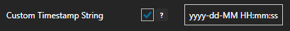
Custom Timestamp String
This setting affects the formatting of a Tag’s timestamp string stored in the TimestampString parameter of each Tag.
Here is an example of a timestamp format configuration:
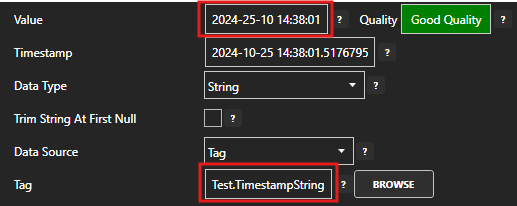
You can see this in action by creating a Tag and setting its data source to Tag and its Tag property to the TimestampString parameter. The Value returned should be in the specified timestamp format.
When enabled, the default timestamp string format is “yyyy-dd-MM HH:mm:ss”.
Default: Disabled
Trending
Longest Realtime Time Frame
This setting configures how much real-time Tag value data OAS will store in memory for each Tag that is configured as a Trend Point by allowing you to adjust the buffer time window. It is important to consider both the size of the time window in seconds as well as how many Trend Point Tags you will create in your OAS instance. The time window you specify will be applied to each Trend Point Tag’s data. The more tags you have the more data has to be stored and the longer the time window the more data is stored per tag. The limitations of this feature essentially translates to how much RAM you have available on your server.
Default: 86400 seconds
Enable Stepped Trend
When enabled, the trend window time range will be divided by the Number of Steps setting below and will only update in increments defined by this calculation. In other words, if a trend window is configured to display 60 seconds of data and the number of steps is 4, it will only update every 15 seconds. This reduces the continuous motion of the trend and makes it easier to read.
Trend controls included in Dotnet Trend and Web Trend will display real-time data when in real-time data mode. This trend window will automatically scroll to the left so that the latest data at the current date and time is displayed on the right hand side of the trend. In other words, the x-axis continuously shifts to keep up with the current time.
By default, a trend window will display 60 seconds of data and will update every second. This means that the trend will move every second. When setting the Number of Steps the 60 seconds will be divided by the number of steps and the result will define after how many seconds the trend will update.
The trend will still show all of the data based on the sample rate.
Default: Disabled
Number of Steps
Defines the update interval of a trend control, calculated based on the number of seconds visible in the time range (x-axis) divided by the number specified by this setting.
For example, if the visible time range is 60 seconds and this setting has a value of 6, then the trend will only refresh the x-axis current time every 10 seconds.
This property is only visible if Enable Stepped Trend is enabled.
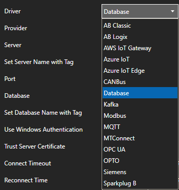
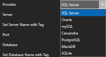
The Database Tag feature adds an additional type of Tag data source to OAS that allows you to integrate a Tag’s value with a database field. It supports many of the common database providers such as SQL Server, Oracle, MySQL, Cassandra, PostgreSQL, MariaDB, and SQLite
NOTE: Database Tags require the Data Logging license to write values to a database and the Recipe – Database Connector license to read values from a database.
There is a clear difference between the Database Tag feature and other database driven features such as Data Historian, Alarm Logging and Recipe.
The Data Historian and Alarm Logging features are stand-alone configurations that will log one or more tags or alarms to a destination database. The aim is to create an independent data record of tag and alarm change history to be consumed by visualizations and external systems.
The Recipe feature is also a stand-alone feature and is designed to read a row of data from a database and copy this data into a batch of Tags. You can think of the data logging features as data storage mechanisms and the Recipe feature as data loader. The former only writes data and the latter only reads data.
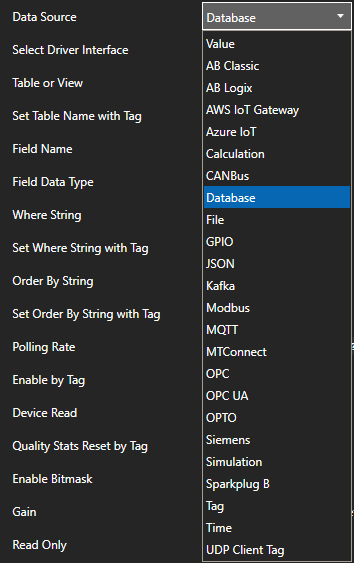
The Database Tag feature on the other hand is not a stand-alone feature, but rather is a Tag data source that is configured as a device driver and then applied at the Tag level. It establishes a one-to-one, read and write relationship between a Tag’s value and a particular database entry as defined by a field name and a query. The driver configuration defines the parameters for the database connection including host and database name. This can then be applied to a Tag by setting the Tag’s Data Source to Database and then configuring the query parameters. The table or view name, field name, Where string and Order By string are all defined at the Tag level.
The following diagram shows an example Tag Col1Tag connected to a database with a table called ProcessData. In plain English, the query that is connected to the Tag’s value can be described as “get me the latest value of Col1 from the ProcessData table where the ProcessID is 1”. Since the Database Tag data source must always return a single value, even if the query returns more than one row, only the top row will be returned. By setting the Order By field to “Timestamp DESC”, the top row will be the latest row.
Sourcing Tag data from a database can be integrated with other OAS features as with any other data source type. For example, you can use Data Route to move your data into another set of Tags that are connected to a device or the Cloud. This allows you to create a data stream from your database and into another device or system. Another great use case is to use Database Tags to add dynamic data to your Open UIEngine screens, such as populating drop-down lists, taking input from text boxes and triggering write actions through button clicks.
The AWS IoT Gateway feature is a data integration driver that an be configured either as a data source or a destination of your Tag data. If you want to receive data from AWS IoT you an set it up to receive data on a particular topic. If you want to publish data to AWS IoT you can configure each individual Tag with a topic or you can bulk publish by adding a list of tags to the AWS IoT driver that should be published. This also gives you the ability construct payloads in JSON format.
The AWS IoT driver supports configuration of the AWS IoT endpoint including the domain, client ID, X.509 certificate encryption as well as store and forward in case communication failure occurs.
If you want to push Tag data sourced from your devices and databases into AWS IoT, you can use the AWS IoT tag publish feature or the Data Route feature to move data from your data source tags into the AWS IoT tags. This is a great way to integrate any of the OAS supported device protocols, such as Modbus, Allen Bradley, Siemens, MT Connect and OPC UA/DA with AWS IoT.
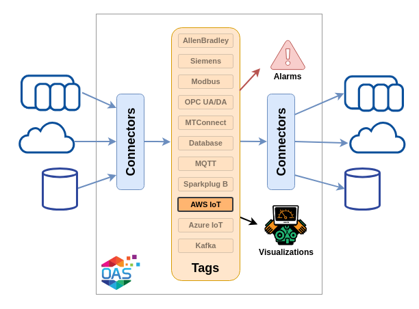
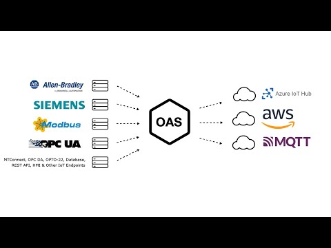
The OAS Cloud IoT Interfaces provide you with the capability to connect and publish tag data to common Cloud IoT service providers and generic MQTT, Kafka and Sparkplug B endpoints. This allows you to push data from any OAS connected industrial device, OPC UA or DA server or client, REST interface, .NET application, web application, database and Excel spreadsheet into the Cloud.
The most common use case for these connectors is to make your devices and databases “Cloud Enabled” and to translate from any of the OAS supported protocols, such as Modbus, Allen Bradley, Siemens, MT Connect and OPC UA/DA, to JSON based messages and publish this data over standard message based push protocols.
AWS IoT Core
The AWS IoT Core connector interfaces with your own private AWS IoT Core broker endpoint. It gives you the ability to publish Tag values into AWS and subscribe to topics in AWS to receive Tag value updates.
Write live data to Azure IoT Hub or Azure Event Hubs. This enables you to take full advantage of any or all of the other big data and IoT services provided by Azure.
The OAS Kafka Connector allows you to send data as a producer and receive data as a consumer via adjustable JSON packet structure with multiple tags per topic.
OAS allows you to apply the Sparkplug B specification to your MQTT messaging infrastructure with the option to create Edge of Network nodes and Primary and Secondary Application nodes. This is included in the MQTT driver.
Define a database table or view as a data source of OAS Tags for read and write access to SQL Server, Oracle, mySQL, MariaDB, SQLite, PostegreSQL, and Cassandra.
You can view the Getting Started with Database Data video to familiarize yourself with the following steps to setup a database interface.
00:00 – Introduction
01:01 – Example Data
01:38 – Configure Connection
03:53 – Save Configuration
04:27 – Configure Tags
05:12 – Read
05:54 – WHERE String
09:26 – Write
09:55 – Examples Tags
10:57 – Watch Window
11:34 – User Interface
13:53 – Data Route
16:03 – Modbus
19:44 – OPC UA
22:33 – Knowledge Base
24:30 – Remote Database
25:15 – Networking
25:48 – Device Drivers
26:10 – UIEngine
26:35 – Getting Started Guide
27:22 – Alarm Limits
28:18 – OpenAutomationSoftware.com
The following guide will demonstrate how to set up a local or remote database connection to enable OAS Tags to access values by column name with static or dynamic table name, WHERE statement, and ORDER BY query.
NOTE: Database Tags require the Data Logging license to write values to a database and the Recipe – Database Connector license to read values from a database.
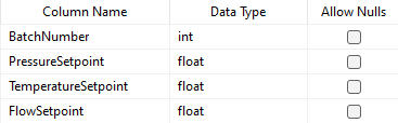
In the steps that follow a connection will be established to a SQL Server database engine to read and write data to a table called Orders that has the following structure.
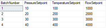
The values in the example table Orders are as follows.
Step 1
Start the Configure OAS application if it is not already running.
Step 2
Select Configure-Drivers to define a database connection.
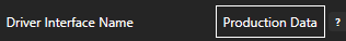
Define a Driver Interface Name that will be used to identify this database connection.
Set the Driver type to Database.
Set the database Provider to the desired selection.
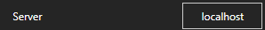
Set the Server property to the local or remote database server. (Not required for SQLite)
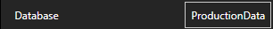
Set the Database property to the name of the database to connect to. For SQLite this is set as the file path of the existing database.
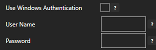
If using SQL Server provider Use Windows Authentication or uncheck to specify User Name and Password for the connection.
To allow writing to the database when a tag is written to enable the property Allow Writing Values.
Note: When tags are written to with a Data Source of Database all records matching the WHERE string of the tag are update. This can result in multiple records being updated from a single write based on the value of the WHERE string of the tag.
Select ADD DRIVER at the left of the list of driver interfaces.
Driver interface is now active in the system and ready for tags to be assigned to the connection.
Select Save on the menu bar to save the configuration changes to the .Tags file.
Step 3
Select Configure-Tags to specify which tables and columns to read and update values.
Select ADD GROUP to optionally define a group where new tags will be added.
In this example we will use the new group name Orders.
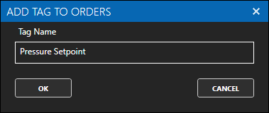
Select ADD TAG to add the tag Pressure Setpoint which will be used to access the values from the PressureSetpoint column.
Set the tag Data Source to Database.
Set the Table or View property to Orders.
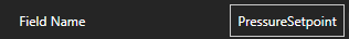
Set the Field Name property to PressureSetpoint.
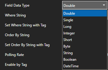
If the field will be updated with a write to the tag set the Field Data Type to the data type of the database column.
Set the Where String property to WHERE BatchNumber = 1.
Note: The value of the Where String property determines which record will be obtained from the table or view. It also determines which record(s) will be updated when a write to the tag occurs.
Select the Apply Changes button to activate the changes to the tag.
The current value of the PressureSetpoint column in the Orders table where the BatchNumber equals 1 will now appear in the tag Value.
Select Save on the menu bar to save the configuration changes to the .Tags file.
Additional Tag Properties
The Order By String property is another property that can be used to determine what record is used to read the value from the database. It is not used in updating records on a write.
The Table or View, Where String, and Order By String properties can optionally be set dynamically from a string tag. The properties Set Table Name with Tag, Set Where String with Tag, and Set Order by String with Tag control the ability to set the respective property values dynamically from another string tag. These properties allow for the determination of which table and record are accessed for reading and updating from other tag values.
The Polling Rate determines the frequency that data is read from the database.
The Enable by Tag property allows control of polling by the value of a Boolean tag; true is enabled, and false is disabled.
The Device Read property enables reading from the database by event instead of continuously. When enabled the Boolean tag that is defined to the Device Read will trigger a read with a value transition from false to true.